CNC Woodworking Project Foundations · KB-014
Upcut, Downcut and Compression Bits for CNC Routers
Choose flute direction by chip evacuation, top and bottom surface quality, cut depth and the real geometry of the router bit.
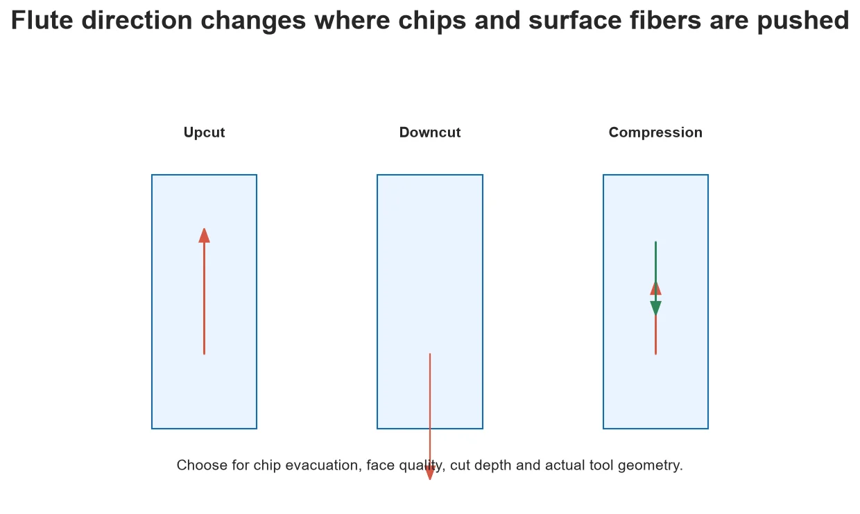
The words upcut, downcut and compression describe how helical cutting edges direct chips and forces. They do not guarantee a clean result by themselves. Material, depth, entry, workholding, extraction and the location of each flute section decide what the surface actually experiences.
Upcut geometry
An upcut tends to move chips upward, helping evacuation from slots and pockets. That flow can lift fibers on the top face or add upward force to poorly retained stock. A suitable tool, sharp edge and finishing allowance can still produce good work, but the word upcut is not a substitute for testing.
Downcut geometry
A downcut tends to press top fibers toward the work, often protecting the upper face. Chips can be driven deeper into a slot, increasing recutting and heat when extraction is weak. Downward force does not make workholding optional; separated parts and warped sheets still require positive control.
Compression geometry
A compression cutter combines opposite helix directions so suitable engagement pushes both outer faces toward the panel core. The transition location matters. If a shallow first pass uses only the upcut portion, the expected top-face benefit may not appear. Confirm cutting length, transition and minimum practical engagement from the actual tool documentation.
Entry and pocket limitations
A cutter optimized for profile edges may not plunge or clear a closed pocket well. Use a supported ramp, pre-entry or toolpath strategy. Keep the complete flute and shank geometry in mind; forcing chips through a narrow slot can overheat material and cutter.
Test with the intended stack
Use a coupon from the actual panel, with the show face oriented as production will be. Cut straight and curved edges at representative depth, inspect both faces and record extraction, feed, speed, stepdown and tool projection. Replace a damaged edge rather than tuning around it.
Choose from the failure you must prevent
An upcut may favor chip removal while lifting the top edge; a downcut may protect the top while pushing debris into the cut. Compression geometry can protect both faces only when the cutting depth places the transition appropriately. Confirm the specific tool geometry and operating limits with its manufacturer.
Run a labeled edge-quality test
Cut short samples at the planned orientation and depth, then label the top and bottom faces before removing them. Compare tear-out, heat, sound and retained debris. Change one variable at a time. The best-looking face is not enough if chips remain packed in the slot or the workholding becomes unreliable.
Decision table
| Bit type | Typical advantage | Main tradeoff |
| Upcut | Chip evacuation | Can lift top fibers and stock |
| Downcut | Top-face support | Can pack chips in deep slots |
| Compression | Supports both panel faces at suitable depth | Transition must be correctly engaged |
| Straight flute | Simple geometry for some materials | Different evacuation and finish behavior |
Worked situation
A compression bit still tears the top veneer on the first pass. Check whether that pass reaches beyond the upcut section, whether the tool is installed at the documented projection and whether the top face is supported. Do not assume the product name guarantees compression at every depth.
Practical checklist
- Identify the show face or faces.
- Check flute transition and cutting length.
- Plan chip evacuation and entry.
- Cut and label a two-face coupon.
Frequently asked questions
Is downcut always best for plywood?
No. Chip evacuation, lower-face quality, depth and workholding also matter.
Can a compression bit cut shallow sheet?
Only if its geometry and required engagement suit the material thickness and toolpath.
Why is the bottom edge rough?
Tool exit, bottom support, spoilboard condition and flute direction can all contribute.
Sources and editorial use
Sources support the technical facts in this original explanation. Their text and images have not been republished.
- 10 Milling Toolpaths for Your First 2D CNC Machining Project — Autodesk Fusion
- Woodworking eTool: Routers — U.S. Occupational Safety and Health Administration
- Wood Handbook: Wood as an Engineering Material — USDA Forest Products Laboratory


