CNC Router Fundamentals · KB-007
CNC Feeds, Speeds and Chip Load Without Guessing
Use the relationship between RPM, flute count and chip load to choose a documented starting feed and refine it for the real machine.
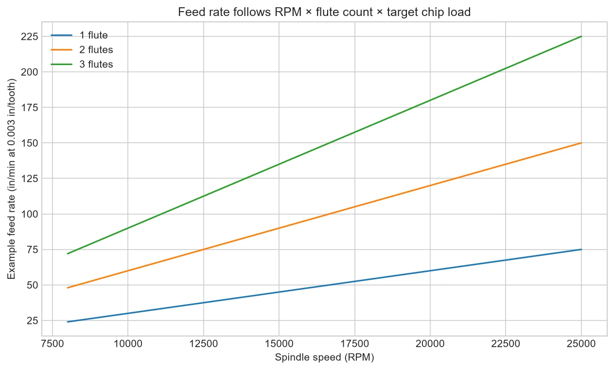
Feed rate and spindle speed should not be adjusted as unrelated knobs. Chip load connects them: it is the programmed advance per cutting edge for each spindle revolution. The calculation provides a starting relationship, while the tool maker, material and actual setup provide limits.
The core relationship
For inch units, feed in inches per minute equals spindle RPM × number of effective flutes × target inches per tooth. Keep units consistent and count only cutting edges that actually engage as intended.
Why slowing feed can make heat worse
Reducing feed while leaving RPM high lowers chip thickness. The edge may rub instead of forming an efficient chip, producing heat and dust. The answer is not always to feed faster; it is to restore a suitable combination within machine and tool limits.
Where starting values come from
Use the cutter manufacturer's data for the tool geometry and material, then account for machine rigidity, tool projection, radial engagement, axial depth, hold-down and extraction. Autodesk also recommends beginning with supplier guidance.
Refine with evidence
Change one controlled variable at a time, observe sound, chip form, spindle load, finish and dimensional result, and record the complete setup. Stop when retention, temperature, vibration or tool behavior is unsafe or uncertain.
Work through a calculation without turning it into a recommendation
Assume a two-flute cutter, 18,000 RPM and a supplier-supported target of 0.003 inch per tooth for the exact tool and material. The relationship gives 18,000 × 2 × 0.003 = 108 inches per minute. This only connects three values. It does not prove the machine can accelerate to that feed in short geometry, that the chosen depth is suitable, or that extraction can clear chips. A valid setup must include those constraints and remain inside every manufacturer limit.
Account for actual motion
A controller may command the programmed feed but slow in tight corners, short segments or limited-acceleration moves. RPM may also differ from the setting under load. Effective chip thickness can therefore fall during parts of the path. Adaptive or constant-engagement strategies aim to control load, but they still require correct setup. Use controller information, spindle feedback where available and observed chips to understand what the machine actually did rather than recording the programmed values alone.
Diagnose heat systematically
Dark edges or a hot tool can result from rubbing, a dull edge, excessive RPM for actual feed, poor chip evacuation, recutting dust, too much engagement or excessive runout. Changing only feed can hide one cause and create another. Inspect the cutting edge and collet, verify extraction, compare straight sections with corners and note whether heat appears immediately or accumulates. Stop before heat creates fire risk or damages the holder and material.
Create a shop parameter record
Store material and grade, cutter manufacturer and part number, diameter, flute count, projection, RPM, feed, plunge, stepdown, stepover, entry, cutting direction, machine, workholding and outcome. Mark values as supplier starting point, tested setup or experimental. This distinction prevents a value copied from another machine from looking like an approved recipe.
Decision table
| Variable | If changed alone | What else to review |
| RPM increases | Chip load decreases at same feed | Tool speed limit, heat and torque |
| Feed increases | Chip load increases at same RPM | Machine acceleration and cutting force |
| Flute count increases | Chip load decreases at same feed/RPM | Chip space and effective flutes |
| Stepdown increases | More axial engagement | Rigidity, flute length and evacuation |
| Stepover increases | More radial engagement | Load, strategy and finish |
Worked situation
A job burns only in small inside corners. The straight-line feed may be appropriate, but the controller slows while RPM remains high. Review corner strategy, acceleration and toolpath smoothing rather than increasing the global feed beyond what straight sections and workholding can support.
Practical checklist
- Confirm units and actual tool diameter.
- Record RPM, flutes and target chip load.
- Check manufacturer limits.
- Document depth, stepover and observed result.
Frequently asked questions
Is chip load the same as depth of cut?
No. Chip load is feed per cutting edge per revolution; depth and stepover describe engagement.
Can the same chip load be used for every diameter?
No. Use tool-specific guidance and validate the full setup.
What if the spindle cannot run slowly enough?
Choose a suitable tool, flute count, feed or spindle for the operating range rather than forcing an invalid combination.
Sources and editorial use
Sources support the technical facts in this original explanation. Their text and images have not been republished.
- Speeds and Feeds for New CNC Machinists — Autodesk Fusion
- Woodworking eTool: Routers — U.S. Occupational Safety and Health Administration


