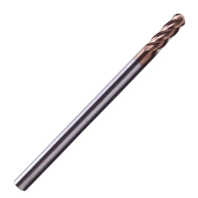
CNC Router Bits and Tool Selection · KB-033
Flat End Mill vs Ball Nose: Choosing the Correct CNC Tool Tip
Compare flat and ball-nose geometry for pocket floors, profiles, 3D surfaces, finishing contact and remaining material.
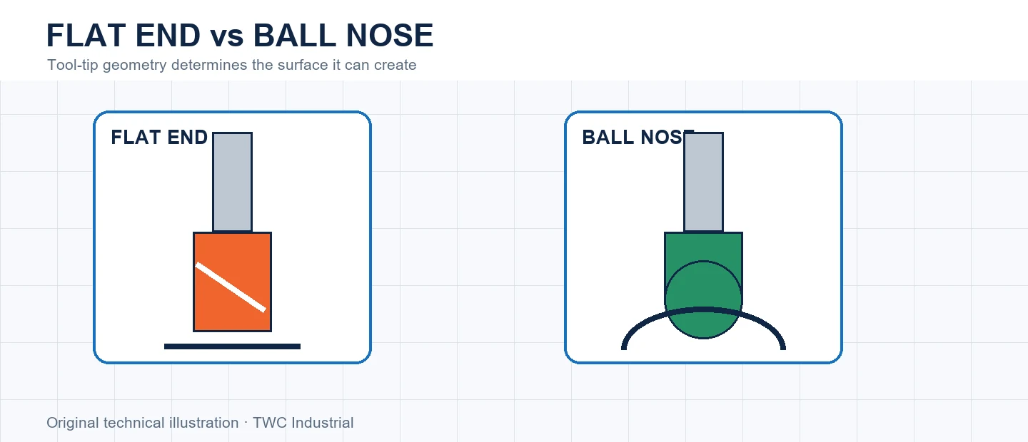
A flat end mill creates planar floors and boundaries. A ball nose provides a continuous radius for many 3D contours but leaves scallops whose height depends on stepover and surface slope. Neither tip is universally the finishing tool.
Understand the physical relationship
Flat tools suit many pockets, profiles and planar features. Ball-nose contact changes continuously around its radius and can follow contoured surfaces without a sharp tip transition. The center behaves differently from its outer region, particularly on shallow surfaces.
Connect geometry to the cut
A large ball tool can finish broad surfaces quickly but miss narrow valleys. A small tool reaches more detail but increases time and may flex. A flat tool can leave step-like transitions on changing slopes. Remaining-stock analysis helps assign each tool where it adds value.
Choose for the complete application
Separate roughing, broad finishing and detail cleanup. Set stepover from surface-quality intent and verify it on shallow and steep regions. Inspect the physical tip; a chipped corner or damaged radius invalidates the tool-library shape.
Run a controlled comparison
Cut representative geometry in the intended material before committing valuable stock. Hold tool identity, projection, workholding and origin constant while changing one relevant variable. Record chips, sound, heat, edge condition and measured geometry. For flat end mill vs ball nose: choosing the correct cnc tool tip, a completed path is not enough; the result must show that tip geometry creates the required surface with controlled remaining stock. Keep the inspected coupon, photograph and CAM revision together.
Create a traceable tool record
Record manufacturer, part number, cutting diameter, shank, cutting length, flute form and measured projection. Add the tested material and operation rather than labeling the cutter only by color or drawer. Tip shape changes contact, reach and texture between passes. Do not transfer an unexplained offset or operating value to a visually similar tool.
Interpret the evidence before changing CAM
If the cut differs from expectation, separate tool geometry from machine calibration, material variation, workholding and engagement. Measure more than one feature and inspect whether error changes with depth, direction or time. A consistent size offset suggests a different investigation from a mark repeating once per revolution or heat appearing only in corners. For this topic, tip shape changes contact, reach and texture between passes. Correct the identified layer, repeat the controlled coupon and document the comparison instead of accumulating compensating settings whose purpose is no longer known.
Verify the full cutting envelope
Recalculate and simulate the cutter, shank and holder at the deepest feature, entry and retract. Confirm the physical tool matches the library and posted program. Review workholding, extraction, guarding and stop controls. A safe-looking centerline cannot prove the collet nut, dust shoe or released stock will remain clear.
Decision table
| Surface | Flat end | Ball nose |
| Pocket floor | Direct flat result | Curved contact |
| Vertical profile | Common choice | Usually not primary |
| 3D contour | May leave steps | Continuous radius |
| Narrow valley | Diameter limits access | Diameter still limits access |
Worked situation
A relief is smooth on steep walls but striped on shallow areas. Review ball-nose stepover and slope, then test a smaller stepover on a representative patch.
Practical checklist
- Identify surface zones.
- Choose diameter for access.
- Preview scallops.
- Inspect the tip.
Frequently asked questions
Can a ball nose cut a flat area?
It can traverse it, but rounded contact leaves scallops unless the finishing plan accounts for them.
Can a tool-library entry replace cutter documentation?
No. Confirm the exact cutter identity and manufacturer limits, then verify imported values for the actual machine and setup.
Can appearance alone prove a cutter is safe?
No. Isolate power before handling and inspect according to the cutter, collet, spindle and machine manufacturers’ procedures.
Sources and editorial use
Sources support the technical facts in this original explanation. Their text and images have not been republished.
- The Router Way: Tool Selection and Chip Load — LMT Onsrud
- 10 Milling Toolpaths for Your First 2D CNC Machining Project — Autodesk Fusion
- Woodworking eTool: Routers — U.S. Occupational Safety and Health Administration