CNC Router Fundamentals · KB-009
Stepdown vs Stepover in CNC Router Toolpaths
Learn how axial depth and radial engagement affect tool load, machining time, pocket clearing and surface finish.
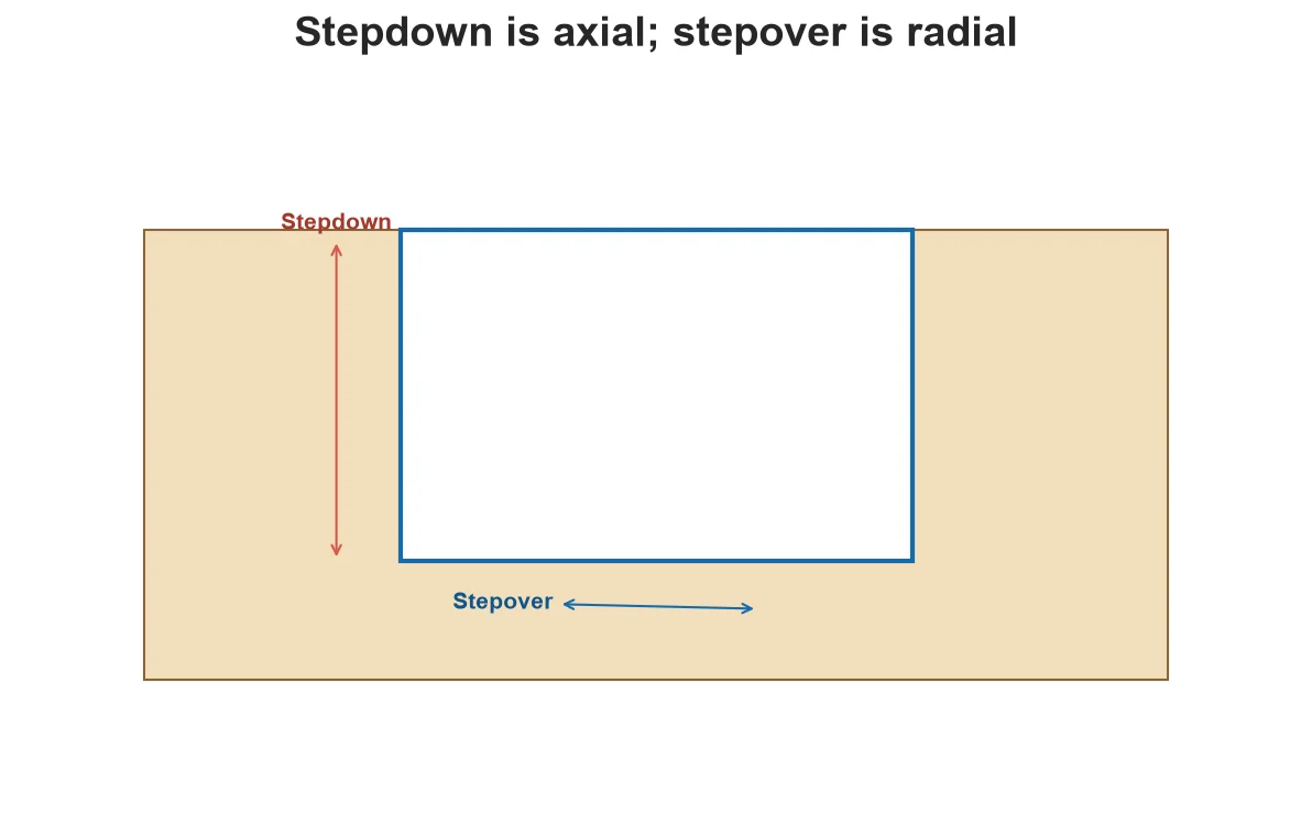
Stepdown and stepover both describe engagement, but in different directions. Stepdown is the axial depth added per level. Stepover is the radial spacing between adjacent passes. Treating them as interchangeable hides the actual cutter load.
Stepdown
A profile deeper than the chosen axial stepdown is cut in several levels. Smaller levels often reduce force but add passes. Maximum practical depth depends on cutter geometry, flute length, projection, machine rigidity and material.
Stepover
Pocketing and surfacing use adjacent passes. Larger stepover removes more width per pass but increases engagement and can change finish. For 3D finishing, stepover also influences cusp height.
Why percentages are incomplete
A percentage of tool diameter is a convenient description, not a universal prescription. Tool type, corner geometry, chip space, spindle power and strategy change what the percentage means in practice.
Build a complete setup record
Record axial depth, radial engagement, feed, RPM, tool, flute count, entry, stock allowance and material. If only feed and speed are saved, the result cannot be reproduced responsibly.
Think in axial and radial engagement together
A shallow stepdown with nearly full-width slotting can load a cutter differently from a deep stepdown with light radial engagement. Neither percentage tells the complete story. Modern clearing strategies may use more flute length with controlled side engagement, while simple profiles can repeatedly engage a large portion of the diameter. Select a strategy supported by CAM behavior, tool geometry, machine rigidity and chip evacuation rather than copying one diameter-based rule into every operation.
Separate roughing and finishing goals
Roughing aims to remove material while preserving tool and setup stability. Leave intentional radial and axial stock when a finish pass is planned. Finishing aims to create the final wall or floor with a controlled amount of material, but an extremely light pass may rub or follow earlier deflection. Document allowance and direction. If the roughing tool deflects, the material left may not equal the CAM setting everywhere.
Check the entire cutting assembly at depth
The flute may be long enough while the larger shank, collet or nut still collides with the wall. Deep pockets also trap chips and reduce air movement. Simulate holder geometry where supported, inspect flute and neck dimensions, and plan evacuation. A longer cutter increases reach but also deflection. Reduce projection where possible and verify that the machine can maintain the intended path without rubbing the holder or recutting packed material.
Decision table
| Goal | Stepdown question | Stepover question |
| Profile roughing | How many axial levels? | How much radial stock/engagement? |
| Pocket clearing | Can chips leave each level? | Does radial load remain controlled? |
| Wall finishing | Is full wall depth suitable? | How much finish stock remains? |
| 3D finishing | How are steep regions handled? | What cusp height/finish results? |
Worked situation
A pocket floor looks good but walls taper. Increasing stepover is unlikely to fix tool bending. Measure wall error by depth, reduce projection, review axial engagement and add a suitable finish pass with controlled stock. The error pattern indicates which engagement direction matters.
Practical checklist
- Check flute length against total depth.
- Confirm holder clearance.
- Match engagement with chip evacuation.
- Use a separate finishing allowance where appropriate.
Frequently asked questions
Is stepover used for an outside profile?
A simple full-depth profile is often described by radial engagement or stock allowance; pocket and clearing paths use explicit pass spacing.
Does smaller always mean safer?
Not always. Extremely light engagement can rub, while extra passes add heat and time.
Can CAM choose these automatically?
CAM can suggest defaults, but the user must validate them for the actual tool, machine and setup.
Sources and editorial use
Sources support the technical facts in this original explanation. Their text and images have not been republished.
- 10 Milling Toolpaths for Your First 2D CNC Machining Project — Autodesk Fusion
- Speeds and Feeds for New CNC Machinists — Autodesk Fusion


