CNC Toolpaths and Cutting Operations · KB-028
CNC Clearance, Retract and Top Heights Explained
Set CAM heights from measured stock, fixtures and machine travel so rapid moves clear obstacles without wasting motion or exceeding limits.
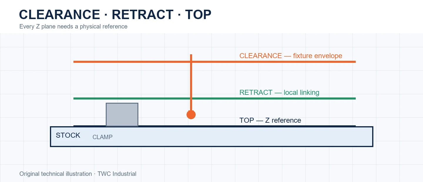
CAM height settings govern where cutting begins, where linking moves occur and what rapid travel is expected to clear. Higher is not automatically safer: excessive Z can hit a soft limit, consume time or expose another configuration error. Every plane needs a physical reference.
Separate the planes
Stock top describes material, retract height controls local linking and clearance height is intended to clear broader obstacles. Names differ between CAM systems. Read the definition and preview actual motion rather than assuming two similarly named fields behave alike.
Measure the obstacle envelope
Fixture height is not only the clamp tip. Include handles, fasteners, workpiece bow, dust collection and the spindle assembly. Obstacles can enter the path after a part is released or a clamp is repositioned, so the setup record must match the current state.
Respect total Z travel
A long tool at a high clearance plane may approach the upper limit; the same setup at final depth may bring the collet near the stock. Simulate holder geometry and compare programmed extremes with homed travel and tool projection.
Run a controlled comparison
Create a small test that reproduces the important geometry from this operation before applying it to a full sheet or valuable blank. Keep the tool, projection, stock, workholding and origin unchanged while comparing one setting at a time. Inspect dimensions, edge condition, floor or wall marks, chips, heat and any movement. In cnc clearance, retract and top heights explained, the useful result is not simply that the program completed; it is evidence showing why one setup behaved better. Retain the test file, photograph and measurement with the CAM revision. If the outcome varies, investigate heights interact with fixtures, tool length, origin and machine travel. before creating a compensating number that hides the cause.
Turn the setting into a shop record
Save the CAM strategy, tool identity, measured stock, origin, workholding and postprocessor with the result. Record what was inspected and what changed. A screenshot of one dialog is incomplete because heights interact with fixtures, tool length, origin and machine travel. Reproducibility comes from the complete setup, not a remembered number.
Verify before committing the workpiece
Recalculate and simulate after every material change. Review the cutter, holder, rapid moves, retracts, remaining stock and order of operations. When appropriate, perform a controlled verification away from the work before cutting. Stop for unexpected sound, movement, heat, dust escape or a path that does not match the preview.
Decision table
| Plane | Purpose | Verification |
| Top | Reference cutting surface | Measured datum matches CAM |
| Retract | Local linking clearance | Clears nearby stock |
| Clearance | Broader rapid safety | Clears full fixture envelope |
| Bottom | Final cutting depth | No hidden hardware below |
Worked situation
A program faults at the beginning even though the cutter is far above the stock. Its clearance plane plus a long tool exceeds available Z travel. Recalculate from a measured fixture envelope and verify both travel extremes instead of simply disabling limits.
Practical checklist
- Name each height reference.
- Measure highest obstacle.
- Check holder at deepest cut.
- Compare extremes with homed travel.
Frequently asked questions
Is a very high clearance plane safest?
No. It may exceed travel and does not replace an accurate obstacle model.
Can simulation prove that a toolpath is safe?
No. It can reveal geometry and sequencing problems, but it cannot prove workholding strength, machine condition, tool retention or extraction performance.
Should a new operation begin at production speed?
Use documented tool guidance and a controlled verification appropriate to the machine, material and setup. Keep the first run under direct supervision.
Sources and editorial use
Sources support the technical facts in this original explanation. Their text and images have not been republished.
- 10 Milling Toolpaths for Your First 2D CNC Machining Project — Autodesk Fusion
- LinuxCNC Important User Concepts — LinuxCNC
- Woodworking eTool: Routers — U.S. Occupational Safety and Health Administration


