CNC Toolpaths and Cutting Operations · KB-027
CNC Lead-In and Lead-Out Moves: Protecting the Finished Edge
Place entry and exit moves where they have clearance, reach stable cutting conditions and avoid visible dwell or witness marks.
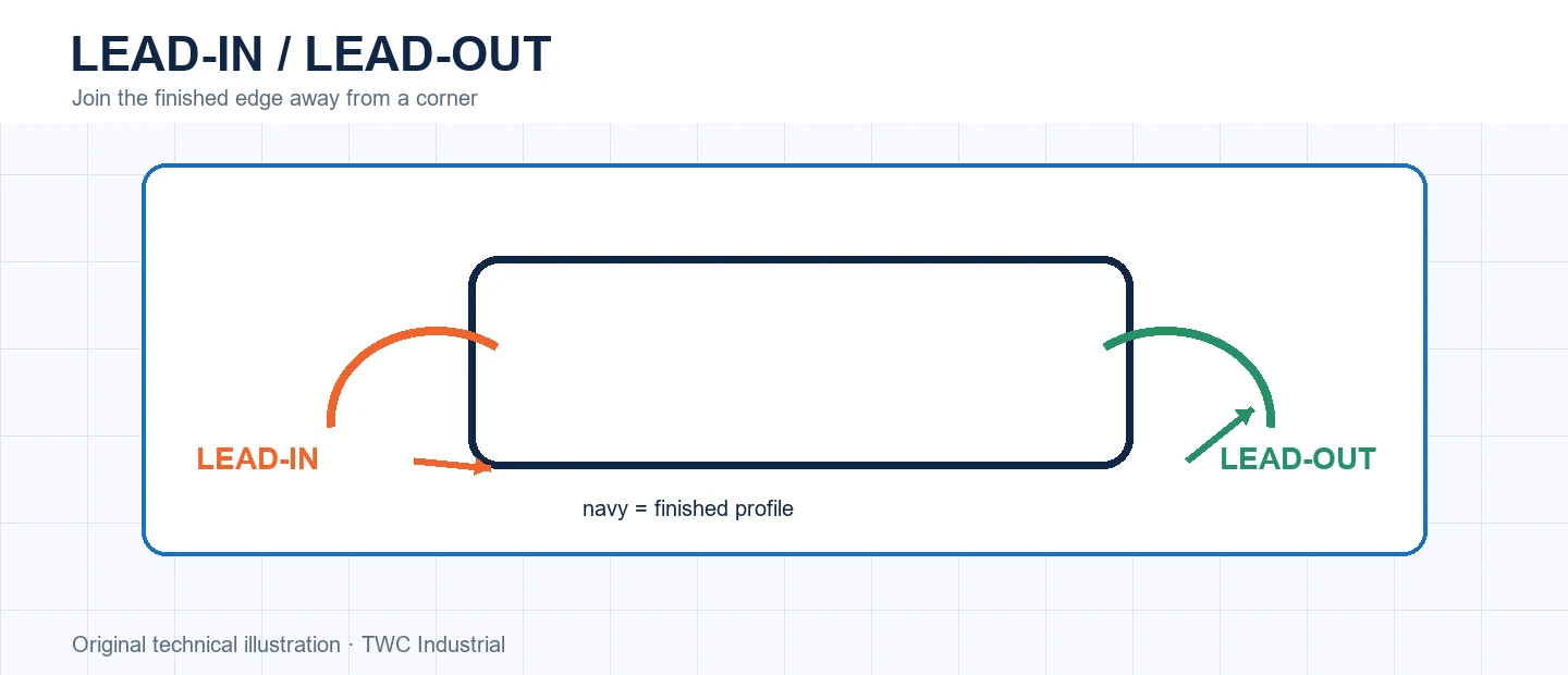
A profile must join and leave its finished boundary somewhere. Lead moves shift that transition away from a blunt plunge on the edge, but a poorly placed lead can cross a clamp, enter missing stock or mark the very surface it was meant to protect.
Give the move physical room
Lead length and radius must fit within remaining stock. On internal features, available space may be much smaller than it looks. Inspect the cutter center, full diameter and any material already removed by earlier operations.
Choose a quiet location
Avoid cosmetic focal points, sharp corners and fragile short segments. A straight section often makes a witness mark easier to blend and inspect. Entry location also affects grain interaction and whether chips can escape.
Understand compensation entry
Controller cutter compensation may require a suitable entry move before the offset is fully established. LinuxCNC documents minimum entry considerations. CAM-computed offsets and controller compensation should not be combined casually; the post and shop method must be explicit.
Run a controlled comparison
Create a small test that reproduces the important geometry from this operation before applying it to a full sheet or valuable blank. Keep the tool, projection, stock, workholding and origin unchanged while comparing one setting at a time. Inspect dimensions, edge condition, floor or wall marks, chips, heat and any movement. In cnc lead-in and lead-out moves: protecting the finished edge, the useful result is not simply that the program completed; it is evidence showing why one setup behaved better. Retain the test file, photograph and measurement with the CAM revision. If the outcome varies, investigate entry geometry depends on both compensation method and remaining stock. before creating a compensating number that hides the cause.
Turn the setting into a shop record
Save the CAM strategy, tool identity, measured stock, origin, workholding and postprocessor with the result. Record what was inspected and what changed. A screenshot of one dialog is incomplete because entry geometry depends on both compensation method and remaining stock. Reproducibility comes from the complete setup, not a remembered number.
Verify before committing the workpiece
Recalculate and simulate after every material change. Review the cutter, holder, rapid moves, retracts, remaining stock and order of operations. When appropriate, perform a controlled verification away from the work before cutting. Stop for unexpected sound, movement, heat, dust escape or a path that does not match the preview.
Decision table
| Placement | Advantage | Concern |
| Long straight edge | Stable transition | Possible witness mark |
| Inside corner | Compact appearance | Limited room and load |
| Scrap side | Protects finished face | Scrap must still exist |
| Pre-cleared area | Low entry load | Operation order dependency |
Worked situation
A finished profile has a small bump at its start point. Inspect whether the lead is too short, tangency is poor or compensation begins on the boundary. Move the transition to clear straight stock and verify the recalculated path.
Practical checklist
- Select a noncritical location.
- Verify lead radius and length.
- Check prior removed stock.
- Inspect compensation and post output.
Frequently asked questions
Must every profile use a curved lead?
No. Geometry, controller method, tool and finish requirements determine the appropriate transition.
Can simulation prove that a toolpath is safe?
No. It can reveal geometry and sequencing problems, but it cannot prove workholding strength, machine condition, tool retention or extraction performance.
Should a new operation begin at production speed?
Use documented tool guidance and a controlled verification appropriate to the machine, material and setup. Keep the first run under direct supervision.
Sources and editorial use
Sources support the technical facts in this original explanation. Their text and images have not been republished.
- LinuxCNC Tool Compensation — LinuxCNC
- Vectric 2D Profile Toolpath — Vectric
- 10 Milling Toolpaths for Your First 2D CNC Machining Project — Autodesk Fusion


