CNC Toolpaths and Cutting Operations · KB-030
CAM Simulation Checklist Before Running a CNC Toolpath
Review tools, stock, coordinates, holder clearance, remaining material and operation order before posting and verifying a CNC program.
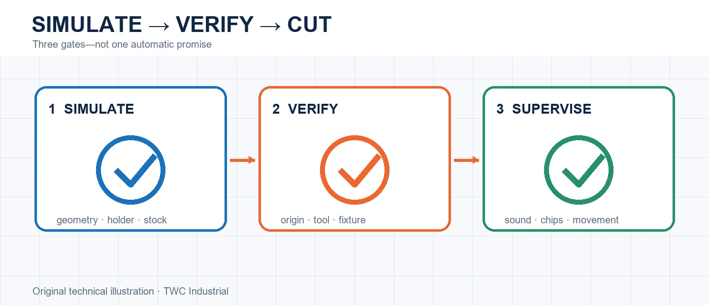
Simulation is a structured review, not a decorative animation. It should answer whether the selected tool removes intended stock, whether moves occur in the expected coordinate frame and whether later operations receive the geometry they need. Physical setup checks remain separate and essential.
Start with setup identity
Confirm units, stock size, orientation, origin, model revision, postprocessor and machine configuration. A beautiful path in the wrong coordinate frame is still wrong. Check that the physical datum can be established as modeled.
Inspect the cutting envelope
Display the tool, shank and holder where supported. Look at deepest pockets, narrow channels, entry moves and transitions. Review remaining stock and collisions with modeled fixtures, but remember that an incomplete fixture model creates false confidence.
Read the sequence as a process
Step through tool changes and operations. Identify loose islands, released parts, disappearing datums and rapids over changing stock. Check warnings rather than dismissing them because the final rendered part looks correct.
Run a controlled comparison
Create a small test that reproduces the important geometry from this operation before applying it to a full sheet or valuable blank. Keep the tool, projection, stock, workholding and origin unchanged while comparing one setting at a time. Inspect dimensions, edge condition, floor or wall marks, chips, heat and any movement. In cam simulation checklist before running a cnc toolpath, the useful result is not simply that the program completed; it is evidence showing why one setup behaved better. Retain the test file, photograph and measurement with the CAM revision. If the outcome varies, investigate the posted and physical setup must match the simulated assumptions. before creating a compensating number that hides the cause.
Turn the setting into a shop record
Save the CAM strategy, tool identity, measured stock, origin, workholding and postprocessor with the result. Record what was inspected and what changed. A screenshot of one dialog is incomplete because the posted and physical setup must match the simulated assumptions. Reproducibility comes from the complete setup, not a remembered number.
Verify before committing the workpiece
Recalculate and simulate after every material change. Review the cutter, holder, rapid moves, retracts, remaining stock and order of operations. When appropriate, perform a controlled verification away from the work before cutting. Stop for unexpected sound, movement, heat, dust escape or a path that does not match the preview.
Decision table
| Review layer | Question | Evidence |
| Setup | Is the coordinate frame correct? | Named origin and units |
| Tool | Is geometry and projection correct? | Library and measured setup |
| Motion | Do entries and rapids clear? | Sectioned simulation |
| Process | Does stock remain controlled? | Operation-by-operation review |
Worked situation
Simulation shows a correct final shape, but the first rapid crosses a clamp omitted from the CAM setup. Add the actual fixture envelope, recalculate, review holder clearance and then use the shop's controlled verification procedure. Final-shape comparison alone was insufficient.
Practical checklist
- Verify revision, units and origin.
- Inspect cutter and holder.
- Review rapid and retract moves.
- Check stock after every operation.
- Confirm posted program identity.
Frequently asked questions
Should the posted G-code be reviewed too?
Yes. Postprocessing translates CAM intent for a specific controller, so program identity and critical motion deserve verification.
Can simulation prove that a toolpath is safe?
No. It can reveal geometry and sequencing problems, but it cannot prove workholding strength, machine condition, tool retention or extraction performance.
Should a new operation begin at production speed?
Use documented tool guidance and a controlled verification appropriate to the machine, material and setup. Keep the first run under direct supervision.
Sources and editorial use
Sources support the technical facts in this original explanation. Their text and images have not been republished.
- 10 Milling Toolpaths for Your First 2D CNC Machining Project — Autodesk Fusion
- LinuxCNC G-code Quick Reference — LinuxCNC
- Woodworking eTool: Routers — U.S. Occupational Safety and Health Administration


