CNC Toolpaths and Cutting Operations · KB-023
CNC Drilling Cycles: Simple, Dwell and Peck Drilling Explained
Choose a drilling approach by depth, chip evacuation, tool geometry and material instead of applying pecking or dwell to every CNC hole.
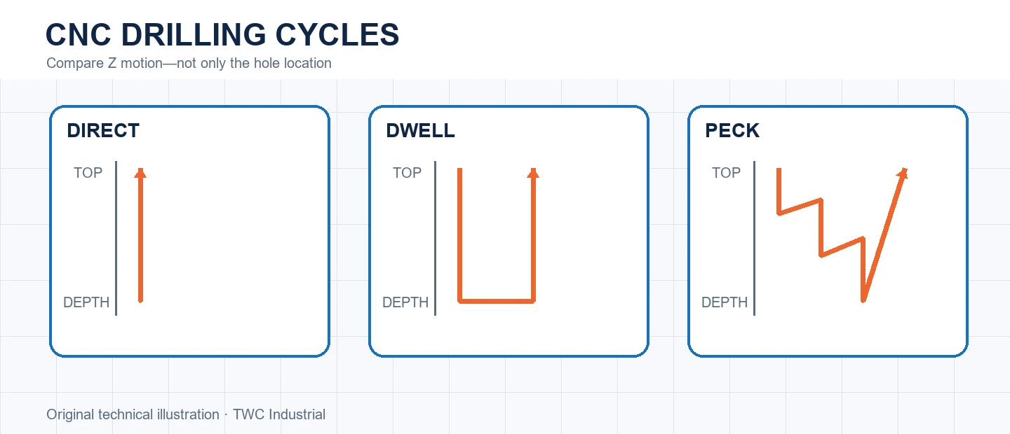
A hole toolpath includes more than its XY location. Feed, depth, retract level, breakthrough, dwell and peck behavior determine how the tool enters, clears debris and leaves the hole. Controller support and postprocessor output must match the intended cycle.
Distinguish the cycles
A basic cycle feeds to depth and retracts. A dwell cycle pauses at depth, which may help a specific operation but can add heat if misused. Peck cycles divide depth into increments; some make small chip-breaking retracts while others return farther for evacuation. Names vary, so inspect posted motion.
Plan the Z levels
The retract plane must clear the surface and local features without wasting motion. Final depth may need controlled breakthrough into sacrificial support. Check clamps, inserts and spoilboard features below every hole. A correct XY pattern can still cause a collision underneath.
Control chips and heat
Packed debris increases rubbing and heat. Tool geometry, depth-to-diameter ratio, material, extraction and feed all matter. More pecks are not automatically safer; they add entries and time. Follow drill and machine guidance, then inspect chips and hole condition.
Run a controlled comparison
Create a small test that reproduces the important geometry from this operation before applying it to a full sheet or valuable blank. Keep the tool, projection, stock, workholding and origin unchanged while comparing one setting at a time. Inspect dimensions, edge condition, floor or wall marks, chips, heat and any movement. In cnc drilling cycles: simple, dwell and peck drilling explained, the useful result is not simply that the program completed; it is evidence showing why one setup behaved better. Retain the test file, photograph and measurement with the CAM revision. If the outcome varies, investigate a drilling result depends on cycle semantics and all of its Z levels. before creating a compensating number that hides the cause.
Turn the setting into a shop record
Save the CAM strategy, tool identity, measured stock, origin, workholding and postprocessor with the result. Record what was inspected and what changed. A screenshot of one dialog is incomplete because a drilling result depends on cycle semantics and all of its Z levels. Reproducibility comes from the complete setup, not a remembered number.
Verify before committing the workpiece
Recalculate and simulate after every material change. Review the cutter, holder, rapid moves, retracts, remaining stock and order of operations. When appropriate, perform a controlled verification away from the work before cutting. Stop for unexpected sound, movement, heat, dust escape or a path that does not match the preview.
Decision table
| Cycle | Useful question | Risk to inspect |
| Direct drill | Can chips leave at this depth? | Packing near bottom |
| Dwell | Is a pause technically required? | Heat and rubbing |
| Chip-break peck | Will a short retract break chips? | Debris remains in hole |
| Deep peck | Is fuller evacuation needed? | Added time and re-entry |
Worked situation
A deep hole darkens near its bottom while shallow holes remain clean. Review depth ratio, debris and posted retract behavior before lowering the feed globally. Test a suitable evacuation cycle and sacrificial breakthrough using the tool manufacturer's guidance.
Practical checklist
- Confirm controller cycle support.
- Inspect retract and final depth.
- Model material beneath the hole.
- Check chips and hole after test.
Frequently asked questions
Does every deep hole need the same peck?
No. Tool, diameter, material, depth and evacuation conditions determine the suitable method.
Can simulation prove that a toolpath is safe?
No. It can reveal geometry and sequencing problems, but it cannot prove workholding strength, machine condition, tool retention or extraction performance.
Should a new operation begin at production speed?
Use documented tool guidance and a controlled verification appropriate to the machine, material and setup. Keep the first run under direct supervision.
Sources and editorial use
Sources support the technical facts in this original explanation. Their text and images have not been republished.
- LinuxCNC G-code Quick Reference — LinuxCNC
- 10 Milling Toolpaths for Your First 2D CNC Machining Project — Autodesk Fusion
- Woodworking eTool: Routers — U.S. Occupational Safety and Health Administration


