CNC Router Fundamentals · KB-006
CNC Router Workholding Methods and When to Use Them
Compare screws, clamps, tape-and-adhesive fixtures and vacuum workholding while planning tool clearance and cutting forces.
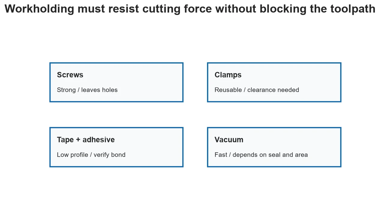
Workholding has one job that contains several requirements: the stock must resist cutting force, remain referenced, stay flat enough for the operation and avoid the cutter. A method that works for one sheet or toolpath may be unsafe for another.
Mechanical fasteners
Screws are strong and inexpensive when holes and a sacrificial bed are acceptable. Place them outside stock-to-leave and toolpaths, use enough edge distance and model their locations so CAM cannot cross them.
Clamps
Edge or top clamps are reusable and visible, but consume clearance. Low-profile fixtures and step clamps can help. The planned cutter, holder and dust shoe must all clear them throughout motion.
Adhesive methods
Tape-and-adhesive fixtures can hold thin parts without top obstruction. Bond quality depends on clean surfaces, compatible materials, area, adhesive condition and removal method. Test conservatively before relying on it.
Vacuum and part retention
Vacuum is fast for suitable sheet work but depends on seal, surface area, permeability and pump capacity. Tabs, onion-skin passes or dedicated fixtures may still be needed as parts become separated from the sheet.
Estimate how the part changes during machining
A full sheet has large contact area and stiffness. After pockets and profiles remove material, the remaining web may flex and each separated part has less area resisting force. Workholding must be evaluated at the weakest stage, not only before the first cut. CAM simulation can show when islands and offcuts become free, but it cannot prove that tape, vacuum or clamps provide enough force. Plan tabs, onion-skin material or a dedicated fixture before reaching that stage.
Create explicit keep-out geometry
Represent screws and clamps in the CAM setup or create conservative keep-out regions. Check not only the cutter centerline but the full cutter diameter, collet nut, spindle body and dust shoe. A safe toolpath can still collide during a rapid or retract move. Fixtures should also remain accessible for tightening and inspection. When positions change, update the setup record instead of relying on a mark that may not match the current program.
Verify the method with a low-risk load test
For a new adhesive, porous sheet or vacuum fixture, test representative material and surface preparation before cutting an important part. Apply load in likely cutting directions while the spindle is stopped and power is controlled. Inspect for peel, sliding and leakage. The test does not certify every dynamic condition, but it can reveal clearly inadequate retention. Increase conservatism for small parts, aggressive entry moves and tools that can pull upward.
Decision table
| Method | Strength | Main limitation | Good planning habit |
| Screws | Strong and inexpensive | Holes and collision risk | Model every screw location |
| Clamps | Reusable and inspectable | Consumes top/edge clearance | Check holder and dust shoe |
| Tape + adhesive | Low-profile support | Surface and peel sensitivity | Test representative bond |
| Vacuum | Fast sheet handling | Seal, area and permeability | Monitor zones and remaining area |
| Tabs/onion skin | Retains separated profiles | Needs finishing and correct thickness | Place for force and access |
Worked situation
A small profile moves only on the final pass. Increasing clamp force at the sheet edge may not help because the part is already separated. Add local retention through tabs, an onion skin, adhesive support or a fixture, and review whether the final cutting direction pulls the part into open space.
Practical checklist
- Estimate likely cutting direction and force.
- Model keep-out zones in CAM.
- Secure offcuts and small parts.
- Perform a clearance check before spindle start.
Frequently asked questions
Are tabs always necessary?
No, but separated parts need a verified way to remain controlled.
Can double-sided tape replace clamps?
Sometimes for suitable light work after testing; it is not a universal substitute.
Why did stock move near the end?
Remaining holding area and stiffness often decrease as the profile is completed.
Sources and editorial use
Sources support the technical facts in this original explanation. Their text and images have not been republished.
- Woodworking eTool: Routers — U.S. Occupational Safety and Health Administration
- 10 Milling Toolpaths for Your First 2D CNC Machining Project — Autodesk Fusion


