CNC Router Fundamentals · KB-010
Your First CNC Router Project: A Checkpoint Workflow
Move from design and CAM to workholding, zero setting, air cutting and inspection without allowing one setup mistake to reach the cutter.
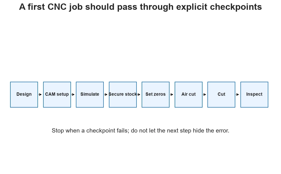
A first project should teach a repeatable process, not merely produce a part once. Use explicit checkpoints so coordinate, tool, depth and workholding mistakes are found while they are still inexpensive and safe to correct.
Design and CAM
Choose simple geometry with a pocket or hole and an outside profile. Define stock size, origin, top surface and tool. Set conservative, documented engagement and heights, then simulate removal and ordering.
Postprocess and review
Use the postprocessor intended for the controller. Check units, active work coordinate, spindle commands, first rapid move, cutting depth, retract height and final move. A CAM simulation cannot prove the postprocessed machine code is safe.
Prepare the machine
Home, inspect the cutter and holder, secure stock, establish the matching work offset and verify extraction and stop controls. Confirm that clamps and fixtures remain outside the complete swept volume.
Prove, cut and inspect
Run a controlled verification above the work when appropriate, then begin the real cut under direct supervision. Inspect dimensions, edge, pocket depth, tool marks and retained stock. Record the complete setup before changing it.
Choose a project that tests the workflow, not every feature
A first job should use inexpensive, consistent stock and geometry that is easy to measure. Limit the number of tools and operations. A shallow pocket plus an outside profile teaches origin, depth, workholding and ordering without adding a complex tool change. Include a known dimension and an orientation mark. The purpose is to prove the chain from design to inspection; decorative complexity can come after that chain is repeatable.
Review postprocessed motion as a separate artifact
Simulation usually represents CAM intent. The machine runs postprocessed code. Verify that the selected post matches the controller, units and machine conventions. Read the opening lines, spindle command, active plane and coordinate system, first approach, minimum Z, retracts and ending move. Compare program extents with stock and machine travel. If unfamiliar commands appear, consult controller documentation rather than deleting them until the file runs.
Use staged proof instead of one start button
After machine and work offsets are verified, use a dry or air verification method appropriate to the machine. Reduce rapid and feed overrides for the first controlled observation where the controller permits. Pause before material engagement and confirm that the tool is above the expected origin. During the real cut, monitor retention, sound, extraction and chip behavior. Never depend on software visualization as the only collision check.
Turn the first result into reusable knowledge
Measure the part before editing compensation. Record nominal and actual size, location, depth, edge condition and any tool marks. Note whether error changes by axis or depth. Photograph the fixture and mark the tested parameter record. If a correction is made, state whether it addresses tool diameter, machine calibration, deflection or stock behavior. This produces a documented setup rather than an unexplained offset that may damage the next project.
Decision table
| Checkpoint | Evidence to retain | Stop condition |
| Design | Drawing and critical dimensions | Unclear units or impossible geometry |
| CAM | Setup sheet and simulation | Wrong origin, tool or depth |
| Machine setup | Fixture and offset record | Unverified retention or clearance |
| Verification | Observed extents and first moves | Unexpected direction or height |
| Inspection | Measured result and notes | Unexplained error before repetition |
Worked situation
If the first pocket is the correct shape but too deep, stop before changing the drawing. Compare CAM bottom height, physical Z reference, tool-length procedure and actual stock thickness. Correcting the identified layer prevents the same error from reappearing in every future file.
Practical checklist
- Use known units and a matching postprocessor.
- Confirm stock origin and Z reference.
- Verify workholding and tool clearance.
- Inspect the first part before repeating the job.
Frequently asked questions
What is a good first project?
A simple plate, sign blank or organizer component with limited operations and inexpensive material.
Does simulation make an air cut unnecessary?
No single check catches every error. Use verification appropriate to the machine and risk.
Should a beginner leave the machine running?
No. Active supervision and readiness to stop are essential, especially during a new program.
Sources and editorial use
Sources support the technical facts in this original explanation. Their text and images have not been republished.
- 10 Milling Toolpaths for Your First 2D CNC Machining Project — Autodesk Fusion
- LinuxCNC Important User Concepts — LinuxCNC
- Woodworking eTool: Routers — U.S. Occupational Safety and Health Administration
- DeskProto Free CNC Models — Delft Spline Systems


