CNC Toolpaths and Cutting Operations · KB-026
CNC Stock to Leave: Using Finish Allowance Without Guesswork
Use radial and axial stock allowances deliberately, verify their sign and connect them to a separate finishing and inspection plan.
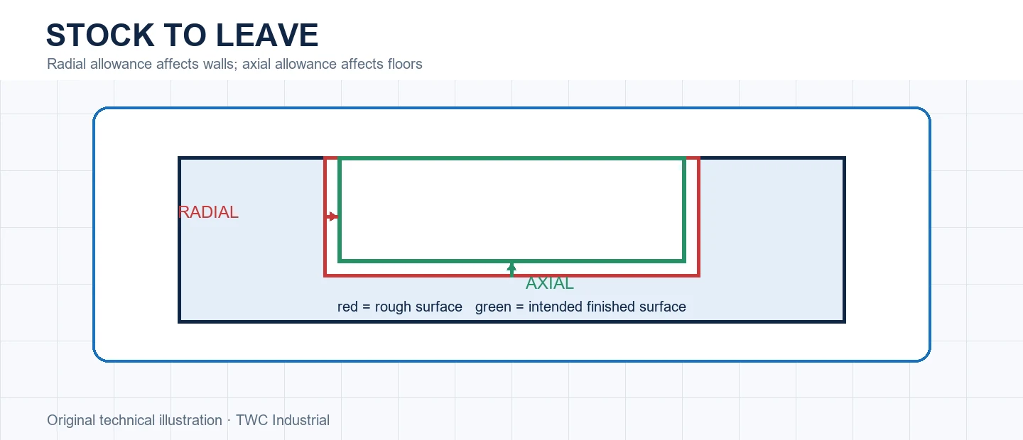
Stock to leave is intentional material between a rough path and the final surface. Radial allowance affects walls; axial allowance affects floors or depths. Confusing their direction or sign can create an oversized part, undersized pocket or unexpected full-width finish cut.
Name the surface being protected
A pocket wall, pocket floor and external profile do not share the same geometric direction. Review the simulated remaining material, not only the numeric field. Color comparison or section views help reveal whether stock exists on the intended side.
Leave enough, but not randomly
Allowance should cover roughing marks and expected variation without making the finish pass unnecessarily heavy. Tool condition, rigidity, material and roughing consistency matter. A universal allowance copied between machines is not a controlled standard.
Do not hide dimensional compensation
Stock to leave is a process-planning value, not a permanent correction for wrong tool diameter or calibration. If a finished dimension is wrong, identify whether geometry, tool definition, deflection or measurement caused it before applying an unexplained offset.
Run a controlled comparison
Create a small test that reproduces the important geometry from this operation before applying it to a full sheet or valuable blank. Keep the tool, projection, stock, workholding and origin unchanged while comparing one setting at a time. Inspect dimensions, edge condition, floor or wall marks, chips, heat and any movement. In cnc stock to leave: using finish allowance without guesswork, the useful result is not simply that the program completed; it is evidence showing why one setup behaved better. Retain the test file, photograph and measurement with the CAM revision. If the outcome varies, investigate allowance has a direction, stage and intended removal operation. before creating a compensating number that hides the cause.
Turn the setting into a shop record
Save the CAM strategy, tool identity, measured stock, origin, workholding and postprocessor with the result. Record what was inspected and what changed. A screenshot of one dialog is incomplete because allowance has a direction, stage and intended removal operation. Reproducibility comes from the complete setup, not a remembered number.
Verify before committing the workpiece
Recalculate and simulate after every material change. Review the cutter, holder, rapid moves, retracts, remaining stock and order of operations. When appropriate, perform a controlled verification away from the work before cutting. Stop for unexpected sound, movement, heat, dust escape or a path that does not match the preview.
Decision table
| Surface | Allowance type | Common mistake |
| Pocket wall | Radial | Wrong sign enlarges pocket |
| External profile | Radial | Part left oversized unintentionally |
| Pocket floor | Axial | Depth remains shallow |
| Top surface | Separate facing plan | Assuming roughing controls it |
Worked situation
An outside part remains 0.5 mm oversized after its supposed final contour. The finish operation inherited roughing stock-to-leave. Remove the allowance from the true finish pass, recalculate and verify the simulated boundary before adjusting the drawing.
Practical checklist
- Identify wall and floor separately.
- Check allowance sign.
- Confirm finish operation removes it.
- Measure against the intended datum.
Frequently asked questions
Is zero stock always a finish pass?
No. Tool engagement, path, feed and entry also determine whether an operation is suitable for finishing.
Can simulation prove that a toolpath is safe?
No. It can reveal geometry and sequencing problems, but it cannot prove workholding strength, machine condition, tool retention or extraction performance.
Should a new operation begin at production speed?
Use documented tool guidance and a controlled verification appropriate to the machine, material and setup. Keep the first run under direct supervision.
Sources and editorial use
Sources support the technical facts in this original explanation. Their text and images have not been republished.
- 10 Milling Toolpaths for Your First 2D CNC Machining Project — Autodesk Fusion
- 2D Adaptive Clearing Reference — Autodesk Fusion
- LinuxCNC Tool Compensation — LinuxCNC


