CNC Router Fundamentals · KB-002
Machine Coordinates vs Work Coordinates on a CNC Router
Learn the practical difference between the G53 machine reference and G54 work offset so CNC jobs start in the intended location.
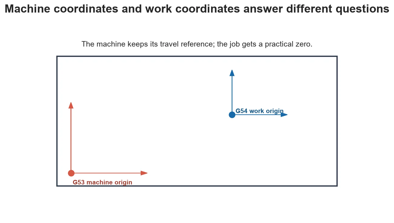
Two zeros can both be correct because they answer different questions. Machine coordinates describe position within known travel. Work coordinates describe position relative to a useful point on the stock, fixture or part. Mixing them is a common reason a valid toolpath moves to the wrong place.
The machine reference
LinuxCNC describes G53 as the machine coordinate system established by homing. It is tied to machine travel and supports soft limits. Operators normally do not program an entire part directly in this system.
The work reference
G54 through G59.3 provide user coordinate systems. G54 is commonly selected for a job, with its origin placed at a stock corner, center, top surface or fixture datum that matches CAM setup.
Why the displayed number changes
The physical axis can remain still while the display changes because the controller is showing the same position through another coordinate system or offset. Always confirm which coordinate view is active.
A repeatable setup
Home the machine, load the intended work offset, establish X and Y from a repeatable datum, establish Z with the correct tool or probe procedure, then verify a known point and clearance move.
Use a coordinate hierarchy instead of one remembered zero
A reliable setup begins with a machine reference, then adds a fixture or work offset, and may add a tool-length relationship. Each layer should be explainable independently. Machine coordinates answer where the axes are within travel. G54 answers where the current job origin sits relative to that machine. Tool length determines where the cutting tip is relative to the spindle reference. If a Z move is wrong, ask which layer changed instead of repeatedly touching off until the display looks familiar. This hierarchy is especially important when several fixtures or tools share one program.
Choose a work origin that survives the job
A stock corner is convenient but may disappear during profiling. The stock top is intuitive for shallow engraving but varies when sheet thickness varies. A fixture pin, machined pocket or spoilboard datum can be more repeatable for production. The best choice is not universal: it should be accessible, represented exactly in CAM and stable through the operations that need it. Record whether the origin is at the stock edge, modeled edge, centerline or fixture feature, and whether Z references stock top, fixture surface or another controlled plane.
Verify offsets without risking the cutter
After setting the offset, command or jog to a known point at a safe Z height and compare the displayed coordinates with the physical setup. Preview the program extents against usable travel. Check that the lowest programmed Z remains above fixtures and below stock top only where intended. If the controller supports a distance-to-go or bounding-box view, use it as supporting evidence rather than trusting it alone. Keep rapid override low for the first move of a new setup and remain ready to stop.
Decision table
| Reference | What it describes | Typical way it is established |
| G53 machine | Position within machine travel | Homing |
| G54 work | Job origin relative to machine | Touch-off, edge finding or probing |
| Tool length | Cutting tip relative to tool reference | Tool setter or measured offset |
| CAM origin | Programmed coordinate assumption | Setup definition in CAM |
Worked situation
A program simulates correctly but begins ten inches to the right. Do not shift the CAD model immediately. Confirm active G54, compare CAM origin with physical touch-off and inspect whether a saved offset from another fixture is active. Correcting the responsible layer preserves a traceable setup.
Practical checklist
- Home before relying on soft limits.
- Match CAM origin to the physical touch-off point.
- Confirm active work offset in the controller.
- Check Z zero and safe retract independently.
Frequently asked questions
Does homing erase G54?
LinuxCNC notes that homing changes the machine reference; it does not itself change user coordinate offsets.
Should Z zero be stock top or machine bed?
Either can work when CAM and setup agree. Stock top is intuitive for many router jobs; fixture-based production may use another datum.
What is G53 used for?
It allows a move expressed in machine coordinates, commonly for safe machine-position moves when used correctly.
Sources and editorial use
Sources support the technical facts in this original explanation. Their text and images have not been republished.
- LinuxCNC Important User Concepts — LinuxCNC
- LinuxCNC Stepper Configuration Wizard — LinuxCNC


