CNC Woodworking Project Foundations · KB-017
Dogbone Fillets for CNC-Cut Wood Joinery
Understand why round router bits leave internal radii and how dogbone or T-bone relief can create assembly clearance without random overcutting.
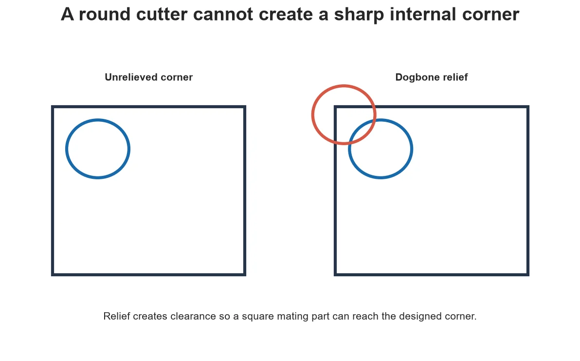
A round cutter cannot remove the last material from a mathematically sharp internal corner. If a square tab must enter that pocket, the inside radius blocks it. Dogbone and T-bone relief deliberately extend the cut so the mating corner can pass.
Separate two fit problems
Slot width controls side clearance; corner relief controls whether a square corner can enter. Enlarging the entire slot to solve an internal radius creates unnecessary looseness. First establish fit with a straight coupon, then add local relief for the corners.
Dogbone and T-bone geometry
Vectric describes dogbone relief as a circular extension positioned around the corner and T-bone relief as an extension to the side, useful in particular width/tool relationships. Names and implementations vary across CAD/CAM tools, so inspect generated vectors and toolpath rather than relying on the label.
Use actual tool geometry
The relief must accommodate the cutter path and mating part, including runout and intended assembly clearance. Changing cutter diameter without regenerating the joint can leave insufficient relief or create a large visible notch. Parameterize cutter diameter and material thickness where practical.
Protect strength and appearance
Relief removes material beyond the nominal corner. On a narrow tab, near a fastener or in visible furniture, its location can weaken or distract. Rotate or relocate the relief, change joint style or use a smaller suitable cutter when the design cannot tolerate the notch.
Test an assembly coupon
Cut several slots and tabs with small controlled fit changes in representative material. Label each before removing it from the sheet. Test by hand without hammering, then inspect veneer damage and corner contact. Use the chosen value in the project model and retain the coupon record.
Start from assembly intent
Identify which external corner must enter each internal corner and where extra clearance is acceptable. A dogbone is a functional relief, not decoration. Its direction affects appearance, edge strength and tool access, so choose the style in context and inspect the assembled joint rather than judging the profile alone.
Keep cutter assumptions synchronized
Relief geometry must match the cutter used to make it. If the CAM tool diameter changes while the drawing remains fixed, the joint can become too tight or unnecessarily open. Store the tested cutter, measured material thickness and clearance with the project, then recut a coupon whenever one of those inputs changes.
Decision table
| Problem | Wrong shortcut | Better correction |
| Tab stops at corner | Widen entire slot | Add local cutter-radius relief |
| Joint loose along sides | Add more dogbone | Adjust fit allowance with coupon |
| Relief too visible | Ignore because CAM allows it | Change placement, joint or cutter |
| New cutter used | Reuse old vectors | Regenerate parameterized relief |
Worked situation
A plywood tab enters halfway and jams while the slot width measures correctly. Marker transferred only at the internal corners. Add correctly sized local relief and recut a coupon; do not enlarge the full slot and lose side support.
Practical checklist
- Confirm actual cutter diameter.
- Separate fit allowance from corner relief.
- Review strength and visible surfaces.
- Cut and label an assembly coupon.
Frequently asked questions
Does every CNC joint need dogbones?
No. Rounded mating parts, open corners or other joint designs may not require them.
Can a smaller bit solve the corner?
It reduces the radius but cannot create a perfectly sharp internal corner.
Why use a T-bone?
It can move relief to a side or accommodate particular slot/tool geometry; verify the implementation.
Sources and editorial use
Sources support the technical facts in this original explanation. Their text and images have not been republished.
- Vectric Create Fillets — Vectric
- 10 Milling Toolpaths for Your First 2D CNC Machining Project — Autodesk Fusion
- Wood Handbook: Wood as an Engineering Material — USDA Forest Products Laboratory


