CNC Accuracy, Calibration and Inspection · KB-045
CNC Spindle Tram: Reading an Indicator Sweep Across the Table
Understand front-back and left-right tram, indicator sweep geometry, table reference and the finish patterns caused by angular misalignment.
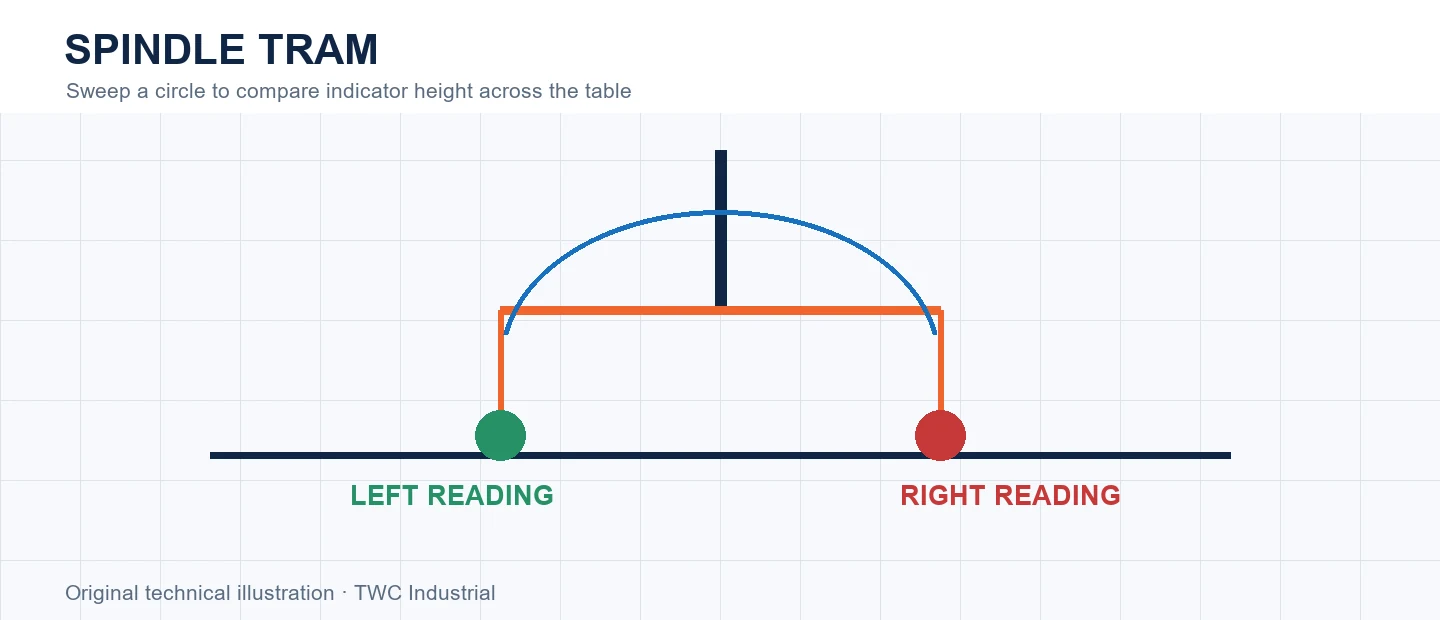
Spindle tram describes the spindle axis orientation relative to the machine's working plane. An indicator swept through a circle compares surface height around the spindle, revealing angular difference that can leave ridges during surfacing.
Define what the test can establish
A sweep radius converts angular tilt into opposite indicator readings. Larger radius amplifies the difference but also demands more clear area and a trustworthy reference surface. Tram is not the same as spindle runout: one concerns axis orientation, the other rotating concentricity.
Control the measurement
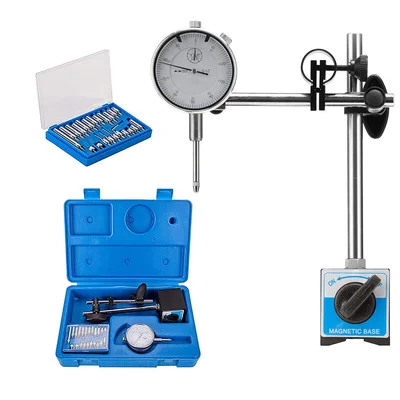
Isolate the spindle from powered rotation and use the machine manufacturer's procedure. Mount the indicator rigidly, preload it appropriately and sweep without striking clamps or holes. Clean the reference and compare opposite points at a stated radius.
Read the error pattern
Opposite high and low readings indicate tilt in that direction. A changing or nonrepeatable reading can come from loose mounting, table debris, bearing play or a poor reference. Surfacing stripes alone cannot quantify tram because cutter geometry and flex also contribute.
Use a repeatable test plan
Record machine state, warm-up condition, location, direction, tool or probe, stock, instrument and operator method. Repeat the measurement rather than keeping only the best result. For cnc spindle tram: reading an indicator sweep across the table, compare magnitude and pattern with the intended tolerance. A result without conditions cannot distinguish a configuration change from temperature, compliance, measurement force or setup variation.
Correct one layer at a time
Begin with the evidence supported by the test. Adjusting from an unstable spoilboard or loose indicator transfers the reference error into the spindle alignment. After a mechanical or configuration change, return to the same artifact and measurement sequence. Avoid stacking CAM offsets, controller compensation and drawing changes because several corrections can cancel at one size while making another size worse.
Separate measurement error from machine error
Repeat the reading without moving the machine, then repeat after returning to the feature through the same path and through the opposite direction when appropriate. This helps distinguish instrument and contact variation from positioning behavior. Compare a second instrument or reference only when its capability and setup are understood. For this topic, Opposite high and low readings indicate tilt in that direction. A changing or nonrepeatable reading can come from loose mounting, table debris, bearing play or a poor reference. Surfacing stripes alone cannot quantify tram because cutter geometry and flex also contribute. Preserve all raw readings because deleting inconvenient values without an identified cause can make an unstable process look calibrated.
Safety and verification boundary
Follow the machine, controller, spindle, probe and instrument manufacturers’ procedures. Isolate energy before mechanical adjustment, keep body parts clear of motion and verify probe inputs and travel limits at controlled speed. Calibration motion and indicator sweeps can still collide with clamps, stock or fixtures. Keep a new routine under direct supervision.
Decision table
| Reading | Meaning | Check |
| Left high/right low | Tilt across X | Adjustment method |
| Front high/back low | Tilt across Y | Gantry/spindle mount |
| Nonrepeatable | Setup or play | Indicator mounting |
| All equal | Tram at that radius | Confirm another radius |
Worked situation
A wide surfacing cutter leaves alternating ridges. Sweep a stable reference in X and Y, record radius and readings, then adjust only through the machine's approved alignment points and recheck after tightening.
Practical checklist
- Prepare stable reference.
- Mount indicator rigidly.
- Record sweep radius.
- Check X and Y directions.
Frequently asked questions
Is spindle tram the same as tool runout?
No. Tram is angular orientation to the work plane; runout is off-axis rotation.
Can one successful test prove the machine is calibrated?
No. Repeat the test, vary position where relevant and retain measurements so drift and direction-dependent behavior can be distinguished.
Should compensation be the first response to an error?
No. Inspect mechanics, measurement method, setup and configuration before using compensation to address a diagnosed residual error.
Sources and editorial use
Sources support the technical facts in this original explanation. Their text and images have not been republished.
- New Concepts of Precision Dimensional Measurement for Modern Manufacturing — National Institute of Standards and Technology
- Woodworking eTool: Routers — U.S. Occupational Safety and Health Administration
- 10 Milling Toolpaths for Your First 2D CNC Machining Project — Autodesk Fusion