CNC Accuracy, Calibration and Inspection · KB-046
CNC Tool Length Offsets: Measuring and Applying Tool Tip Position
Understand how tool-length measurement maps different physical cutters to a consistent programmed Z reference without confusing work and tool offsets.
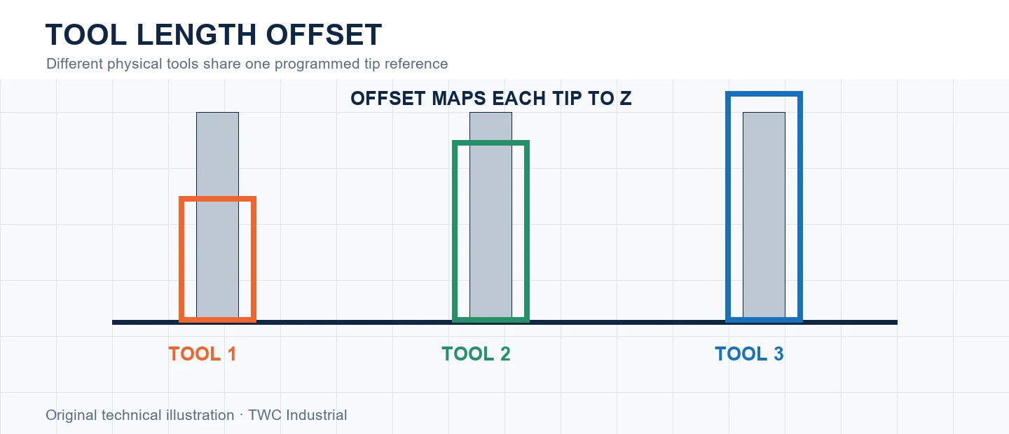
Tool length compensation lets programs refer to a controlled tool tip even when physical cutters have different lengths. The method depends on the controller, holders, gauge reference and whether a tool returns to the same installed length after a change.
Define what the test can establish
A tool table stores a relationship between a tool and reference. When compensation is activated, the controller maps the programmed control point to the tool tip. On systems where a cutter is manually reinserted at a different depth, its effective length must be measured again.
Control the measurement
Use the controller and machine manufacturer's supported procedure. A fixed setter, gauge block or controlled test can establish length only when its reference and contact behavior are known. Probe repeatability, trigger direction, stylus condition and debris all affect the result.
Read the error pattern
Every tool cutting Z wrong by the same amount suggests a work-reference issue; only one tool being wrong suggests its entry, identity or installation. An error appearing after a manual change may indicate a stale offset or changed projection.
Use a repeatable test plan
Record machine state, warm-up condition, location, direction, tool or probe, stock, instrument and operator method. Repeat the measurement rather than keeping only the best result. For cnc tool length offsets: measuring and applying tool tip position, compare magnitude and pattern with the intended tolerance. A result without conditions cannot distinguish a configuration change from temperature, compliance, measurement force or setup variation.
Correct one layer at a time
Begin with the evidence supported by the test. Mixing tool length, work Z and CAM geometry can produce corrections that work for one cutter and fail at the next change. After a mechanical or configuration change, return to the same artifact and measurement sequence. Avoid stacking CAM offsets, controller compensation and drawing changes because several corrections can cancel at one size while making another size worse.
Separate measurement error from machine error
Repeat the reading without moving the machine, then repeat after returning to the feature through the same path and through the opposite direction when appropriate. This helps distinguish instrument and contact variation from positioning behavior. Compare a second instrument or reference only when its capability and setup are understood. For this topic, Every tool cutting Z wrong by the same amount suggests a work-reference issue; only one tool being wrong suggests its entry, identity or installation. An error appearing after a manual change may indicate a stale offset or changed projection. Preserve all raw readings because deleting inconvenient values without an identified cause can make an unstable process look calibrated.
Safety and verification boundary
Follow the machine, controller, spindle, probe and instrument manufacturers’ procedures. Isolate energy before mechanical adjustment, keep body parts clear of motion and verify probe inputs and travel limits at controlled speed. Calibration motion and indicator sweeps can still collide with clamps, stock or fixtures. Keep a new routine under direct supervision.
Decision table
| Symptom | Candidate layer | Verify |
| All tools same Z error | Work offset/reference | Known surface |
| One tool wrong | Tool entry/identity | Remeasure tool |
| Changes after reinsertion | Projection changed | Measurement procedure |
| Offset inactive | Controller state | Program and display |
Worked situation
Tool 1 cuts correct depth but Tool 2 is consistently shallow. Verify Tool 2 identity, installed projection and active length compensation before changing the pocket depth in CAM.
Practical checklist
- Home machine.
- Confirm tool identity.
- Measure from known reference.
- Verify active compensation.
Frequently asked questions
Does a work Z touch-off replace tool-length measurement?
Not in a multi-tool method that relies on individual tool lengths; the controller model must remain consistent.
Can one successful test prove the machine is calibrated?
No. Repeat the test, vary position where relevant and retain measurements so drift and direction-dependent behavior can be distinguished.
Should compensation be the first response to an error?
No. Inspect mechanics, measurement method, setup and configuration before using compensation to address a diagnosed residual error.
Sources and editorial use
Sources support the technical facts in this original explanation. Their text and images have not been republished.
- LinuxCNC Tool Compensation — LinuxCNC
- LinuxCNC G-Code Examples: Grid, Hole and Tool-Length Probing — LinuxCNC
- LinuxCNC G-code Quick Reference — LinuxCNC