CNC Accuracy, Calibration and Inspection · KB-050
CNC Dimensional Errors: Diagnose the Pattern First
Diagnose offset, proportional, reversal, taper and location-dependent errors before changing drawings, cutter values or controller compensation.
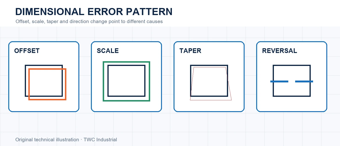
The shape of an error contains diagnostic information. A fixed offset, error proportional to length, direction-dependent shift, taper by depth and variation across the table point toward different layers. Treating every problem as tool diameter creates hidden corrections.
Define what the test can establish
Geometry passes through CAD, CAM, postprocessing, controller configuration, mechanics, tool, workholding and measurement. Each layer produces characteristic evidence. The goal is not to blame one layer quickly but to design the smallest test that separates competing explanations.
Control the measurement
Record nominal, actual, sign, axis, position, depth, approach direction, tool and instrument. Repeat the feature and include a second size. Compare an independent travel measurement when scale is suspected and a reversal test when direction matters.
Read the error pattern
A constant inside/outside relationship implicates tool or offset; proportional error suggests scale; error by depth suggests deflection, tram or shank contact; reversal shift suggests lost motion; location-dependent error suggests geometry, support or screw behavior.
Use a repeatable test plan
Record machine state, warm-up condition, location, direction, tool or probe, stock, instrument and operator method. Repeat the measurement rather than keeping only the best result. For cnc dimensional errors: diagnose the pattern first, compare magnitude and pattern with the intended tolerance. A result without conditions cannot distinguish a configuration change from temperature, compliance, measurement force or setup variation.
Correct one layer at a time
Begin with the evidence supported by the test. A drawing edit can make one feature pass while preserving the underlying error for every future project. After a mechanical or configuration change, return to the same artifact and measurement sequence. Avoid stacking CAM offsets, controller compensation and drawing changes because several corrections can cancel at one size while making another size worse.
Separate measurement error from machine error
Repeat the reading without moving the machine, then repeat after returning to the feature through the same path and through the opposite direction when appropriate. This helps distinguish instrument and contact variation from positioning behavior. Compare a second instrument or reference only when its capability and setup are understood. For this topic, A constant inside/outside relationship implicates tool or offset; proportional error suggests scale; error by depth suggests deflection, tram or shank contact; reversal shift suggests lost motion; location-dependent error suggests geometry, support or screw behavior. Preserve all raw readings because deleting inconvenient values without an identified cause can make an unstable process look calibrated.
Safety and verification boundary
Follow the machine, controller, spindle, probe and instrument manufacturers’ procedures. Isolate energy before mechanical adjustment, keep body parts clear of motion and verify probe inputs and travel limits at controlled speed. Calibration motion and indicator sweeps can still collide with clamps, stock or fixtures. Keep a new routine under direct supervision.
Decision table
| Pattern | Candidate | Discriminating test |
| Fixed offset | Tool/datum | Inside vs outside |
| Proportional | Axis scale | Several lengths |
| Direction shift | Lost motion | Reversal indicator |
| Depth taper | Deflection/tram | Measure by height |
| Location change | Geometry/support | Repeat across table |
Worked situation
A 50 mm feature is 0.1 mm short and a 200 mm feature is also 0.1 mm short. That fixed error does not support proportional axis-scale correction; compare tool definition and offsets first.
Practical checklist
- Record sign and conditions.
- Repeat the feature.
- Compare size/direction/depth.
- Test one candidate layer.
Frequently asked questions
Should CAD be resized to compensate for a machine error?
Not as a first response. Diagnose and correct the appropriate process layer so the design remains truthful.
Can one successful test prove the machine is calibrated?
No. Repeat the test, vary position where relevant and retain measurements so drift and direction-dependent behavior can be distinguished.
Should compensation be the first response to an error?
No. Inspect mechanics, measurement method, setup and configuration before using compensation to address a diagnosed residual error.
Sources and editorial use
Sources support the technical facts in this original explanation. Their text and images have not been republished.
- New Concepts of Precision Dimensional Measurement for Modern Manufacturing — National Institute of Standards and Technology
- LinuxCNC Stepper Diagnostics — LinuxCNC
- LinuxCNC Tool Compensation — LinuxCNC


