CNC Router Fundamentals · KB-001
CNC Router Parts and How They Work Together
Understand the frame, gantry, motion system, controller, spindle, workholding and dust collection that make a CNC router work as one system.
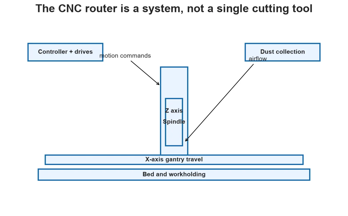
A CNC router is easier to understand when you stop treating it as a mysterious machine and begin treating it as connected subsystems. The controller requests motion, drives and motors create it, the structure guides it, the spindle turns the cutter, workholding resists the cut and dust collection removes debris.
Structure and motion
The bed supports the stock, the gantry spans the work area and linear guides constrain each axis. Motors drive screws, racks or belts. Backlash, loose fasteners, flex and poor alignment anywhere in this chain can appear as dimensional error or rough finish.
Controller and drives
CAM produces toolpaths, a postprocessor converts them to machine instructions and the controller turns those instructions into coordinated axis commands. Motor drives supply controlled power. Configuration errors can look mechanical, which is why test moves and measured travel belong in commissioning.
Spindle and tool holding
The spindle or router supplies rotation. The collet and nut grip the correct tool shank, while bearings support the rotating assembly. Tool projection, runout, speed range and available torque affect what cuts are practical.
The supporting systems
Workholding, spoilboard, electrical protection, guarding and dust extraction are not accessories to ignore. They determine whether the planned toolpath can run without movement, collision, exposure or debris recutting.
Follow the force path when a cut goes wrong
Cutting force begins at the edge, travels through the tool and collet into the spindle, continues through the Z carriage and gantry, and returns through the frame, bed, fixture and stock. A loose connection anywhere in that loop can let the tool and work move relative to each other. If an outside profile is undersized, for example, check whether the error changes with cutting direction, depth or position on the table. Direction-dependent error suggests compliance or backlash; a uniform scale error points more toward calibration or units. This method narrows the search more effectively than replacing the spindle because the finish looks poor.
Match symptoms with the subsystem that can create them
Lost position can come from a motor stall, loose coupling, drive fault or command problem. A repeating ridge may come from runout, a damaged edge or structural vibration. A tapered wall may reflect tool deflection, spindle tram or a stock surface that is not parallel to machine motion. Start with observation: note axis, operation, direction, depth and when the symptom began. Then perform a low-risk test that isolates one part of the chain. Calibration squares, indicator checks and no-load motion tests provide more useful evidence than changing several settings at once.
Create a machine record before creating many jobs
Record usable travel, positive axis directions, homing order, controller units, spindle range, collet sizes, spoilboard reference and the locations of stop controls. Add photographs of wiring labels and sensor orientation for maintenance use, but do not expose sensitive serial numbers publicly. This record becomes the parent reference for future setup and troubleshooting pages. When hardware or firmware changes, create a new version with a date rather than overwriting the old configuration. Versioning makes a Knowledge Base practical in the shop instead of merely descriptive.
Decision table
| Observed symptom | First systems to inspect | Useful first check |
| Dimension changes by direction | Motion transmission, backlash, structure | Reversal test with an indicator |
| Tool marks repeat every revolution | Tool, collet, spindle | Runout and cutting-edge inspection |
| Part moves late in profile | Workholding, tabs, remaining stock | Review force path and retention |
| Position suddenly shifts | Motor, drive, coupling, command | Low-load repeatability test |
Worked situation
Suppose the left side of a panel is accurate but the right side is undersized. Before editing CAM, measure an identical move at several table positions without cutting. If motion is correct unloaded, inspect gantry stiffness, hold-down and cutting direction at the problem area. The location-dependent pattern contains information that a single finished dimension hides.
Practical checklist
- Identify every motion axis and its positive direction.
- Locate emergency stop, limit devices and power isolation.
- Record spindle, collet and tool limits.
- Inspect the complete workholding and extraction path.
Frequently asked questions
Is the gantry the same as the X axis?
Not universally. Builders use different axis naming, so confirm the machine coordinate convention.
Which part determines accuracy?
No single part does. Structure, motion components, calibration, tool holding and setup contribute together.
Can a trim router be upgraded later?
Often yes, but weight, electrical supply, control and mounting must be checked as a system.
Sources and editorial use
Sources support the technical facts in this original explanation. Their text and images have not been republished.
- LinuxCNC Important User Concepts — LinuxCNC
- Woodworking eTool: Routers — U.S. Occupational Safety and Health Administration


