CNC Accuracy, Calibration and Inspection · KB-043
CNC Backlash and Lost Motion: Testing Direction Reversals
Recognize reversal-dependent position error, separate mechanical lost motion from scale error and evaluate correction without hiding wear.
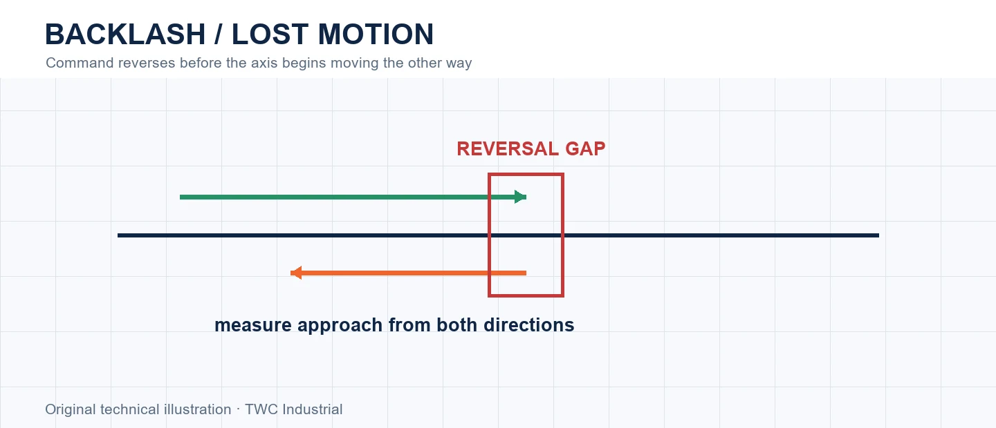
Backlash is one form of lost motion that becomes visible when an axis reverses direction. The command changes immediately, but mechanical clearance or compliance delays actual movement. A one-direction length test can miss it.
Define what the test can establish
Lead screws, nuts, belts, couplings, bearings and structures can contribute reversal behavior. Elastic deflection and loose components may look like backlash but change with force. Software compensation can address a characterized residual in supported systems; it cannot tighten loose hardware or restore worn geometry.
Control the measurement
Preload the indicator or use another suitable method specified for the machine. Move in one direction, reverse by a known command and observe when physical motion begins. Repeat with controlled approach distance, speed and location. Keep the measurement force and mounting rigid.
Read the error pattern
A repeatable gap at reversal differs from proportional scale error that grows with distance. Error changing across travel suggests local wear or alignment. Error changing with acceleration or cutting direction may include compliance, missed motion or tuning rather than simple clearance.
Use a repeatable test plan
Record machine state, warm-up condition, location, direction, tool or probe, stock, instrument and operator method. Repeat the measurement rather than keeping only the best result. For cnc backlash and lost motion: testing direction reversals, compare magnitude and pattern with the intended tolerance. A result without conditions cannot distinguish a configuration change from temperature, compliance, measurement force or setup variation.
Correct one layer at a time
Begin with the evidence supported by the test. Compensation applied before mechanical diagnosis can conceal wear and introduce abrupt correction behavior. After a mechanical or configuration change, return to the same artifact and measurement sequence. Avoid stacking CAM offsets, controller compensation and drawing changes because several corrections can cancel at one size while making another size worse.
Separate measurement error from machine error
Repeat the reading without moving the machine, then repeat after returning to the feature through the same path and through the opposite direction when appropriate. This helps distinguish instrument and contact variation from positioning behavior. Compare a second instrument or reference only when its capability and setup are understood. For this topic, A repeatable gap at reversal differs from proportional scale error that grows with distance. Error changing across travel suggests local wear or alignment. Error changing with acceleration or cutting direction may include compliance, missed motion or tuning rather than simple clearance. Preserve all raw readings because deleting inconvenient values without an identified cause can make an unstable process look calibrated.
Safety and verification boundary
Follow the machine, controller, spindle, probe and instrument manufacturers’ procedures. Isolate energy before mechanical adjustment, keep body parts clear of motion and verify probe inputs and travel limits at controlled speed. Calibration motion and indicator sweeps can still collide with clamps, stock or fixtures. Keep a new routine under direct supervision.
Decision table
| Pattern | Possible source | Next action |
| Fixed reversal gap | Clearance/backlash | Inspect drive stack |
| Error grows with distance | Scale | Travel calibration |
| Changes with load | Compliance/looseness | Mechanical inspection |
| Changes by location | Wear/alignment | Map travel |
Worked situation
A pocket is correct when approached from positive X but shifts after a reversal. Measure reversal behavior with a controlled indicator test before modifying CAD or cutter offset.
Practical checklist
- Secure the indicator setup.
- Approach both directions.
- Repeat across travel.
- Inspect mechanical stack.
Frequently asked questions
Does backlash compensation repair the mechanism?
No. It changes commanded behavior for a characterized error; it does not remove mechanical clearance or wear.
Can one successful test prove the machine is calibrated?
No. Repeat the test, vary position where relevant and retain measurements so drift and direction-dependent behavior can be distinguished.
Should compensation be the first response to an error?
No. Inspect mechanics, measurement method, setup and configuration before using compensation to address a diagnosed residual error.
Sources and editorial use
Sources support the technical facts in this original explanation. Their text and images have not been republished.
- LinuxCNC Stepper Diagnostics — LinuxCNC
- New Concepts of Precision Dimensional Measurement for Modern Manufacturing — National Institute of Standards and Technology
- LinuxCNC Important User Concepts — LinuxCNC


