CNC Router Bits and Tool Selection · KB-031
CNC Router Bit Anatomy: Diameter, Shank, Flute and Cutting Length
Read router-bit dimensions correctly so the cutter, collet, tool library, depth and holder-clearance assumptions describe the same physical tool.
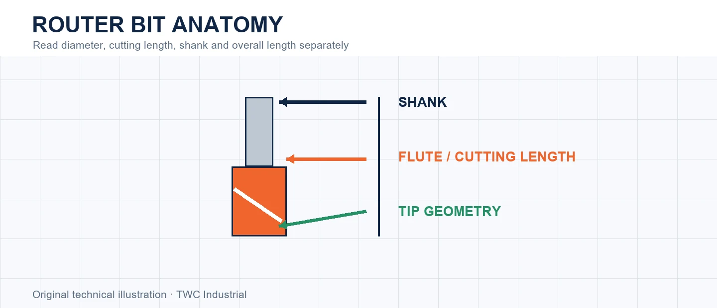
A router bit has several dimensions that answer different questions. Cutting diameter controls the generated edge, shank diameter must match the specified collet, cutting length limits usable flute engagement, and overall length does not equal safe reach.
Understand the physical relationship
Read the cutter from the tip upward. Tip shape creates a flat, radius or angled surface. Flutes make chips along a defined cutting length. A neck or shank above them may not be intended to contact material. Use the manufacturer's dimensioned drawing rather than estimating transitions from a photograph.
Connect geometry to the cut
CAM offsets and corner access rely on cutting diameter. The flute may reach a programmed depth while the shank or collet nut contacts a wall. Conversely, excessive projection reduces stiffness. Model the holder and review the deepest feature, not only the final floor.
Choose for the complete application
Enter cutting diameter, shank, flute count, cutting length and overall length separately. Check units and tool number. Coating color does not identify geometry, and two cutters with the same diameter can have different reach, flute form and entry capability.
Run a controlled comparison
Cut representative geometry in the intended material before committing valuable stock. Hold tool identity, projection, workholding and origin constant while changing one relevant variable. Record chips, sound, heat, edge condition and measured geometry. For cnc router bit anatomy: diameter, shank, flute and cutting length, a completed path is not enough; the result must show that every dimension matches the physical tool and intended contact. Keep the inspected coupon, photograph and CAM revision together.
Create a traceable tool record
Record manufacturer, part number, cutting diameter, shank, cutting length, flute form and measured projection. Add the tested material and operation rather than labeling the cutter only by color or drawer. One incorrect field can alter geometry, collision clearance and load simultaneously. Do not transfer an unexplained offset or operating value to a visually similar tool.
Interpret the evidence before changing CAM
If the cut differs from expectation, separate tool geometry from machine calibration, material variation, workholding and engagement. Measure more than one feature and inspect whether error changes with depth, direction or time. A consistent size offset suggests a different investigation from a mark repeating once per revolution or heat appearing only in corners. For this topic, one incorrect field can alter geometry, collision clearance and load simultaneously. Correct the identified layer, repeat the controlled coupon and document the comparison instead of accumulating compensating settings whose purpose is no longer known.
Verify the full cutting envelope
Recalculate and simulate the cutter, shank and holder at the deepest feature, entry and retract. Confirm the physical tool matches the library and posted program. Review workholding, extraction, guarding and stop controls. A safe-looking centerline cannot prove the collet nut, dust shoe or released stock will remain clear.
Decision table
| Dimension | Controls | Common confusion |
| Cutting diameter | Width and offset | Mistaken for shank |
| Shank | Collet compatibility | Near size treated as equal |
| Cutting length | Flute engagement | Mistaken for reach |
| Overall length | Physical envelope | Assumed safe projection |
Worked situation
A bit is long enough overall for a deep pocket, but flute marks stop halfway down and the shank rubs. Select documented cutting length and review holder clearance instead of extending the same cutter farther.
Practical checklist
- Confirm part number.
- Enter dimensions separately.
- Check cutting length.
- Model holder clearance.
Frequently asked questions
Is overall length the maximum cutting depth?
No. Flute length, holder clearance, machine travel, stiffness and manufacturer limits all matter.
Can a tool-library entry replace cutter documentation?
No. Confirm the exact cutter identity and manufacturer limits, then verify imported values for the actual machine and setup.
Can appearance alone prove a cutter is safe?
No. Isolate power before handling and inspect according to the cutter, collet, spindle and machine manufacturers’ procedures.
Sources and editorial use
Sources support the technical facts in this original explanation. Their text and images have not been republished.
- CNC Router Bit Selection Poster — Amana Tool
- The Router Way: Tool Selection and Chip Load — LMT Onsrud
- How Do I Change the Bit? — Shaper Tools


