CNC Condition Monitoring
Zero-Crossing Rate in CNC Vibration: A Simple Feature with Traps
Understand how zero-crossing rate reflects signal activity and why filtering, offset and noise must be controlled first.
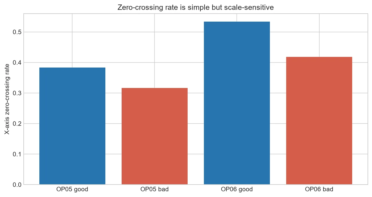
Zero-crossing rate counts how often a centered waveform changes sign. It is simple and inexpensive to compute, but small changes in noise, filtering or offset can change the result substantially.
What crossing rate represents
Faster oscillation often creates more crossings, but a multi-frequency vibration signal has no one-to-one mapping between crossing count and a mechanical frequency.
Noise creates extra crossings
High-frequency electrical noise near zero can add many sign changes without meaningful mechanical change. A documented filter or hysteresis band may improve stability.
Offset removes crossings
A DC shift can hold the waveform above or below zero. Centering by a consistent method is essential, but aggressive detrending can also remove real low-frequency behavior.
Where it can help
The feature can flag broad changes in signal texture or support a small feature set when combined with RMS and spectral measures.
Define the counter before trending
Subtract the window mean, apply the validated filter and count sign changes per second. For a hysteresis version, require the signal to cross both a positive and negative boundary.
Test the feature on healthy records from different days. If ordinary acquisition noise moves it widely, do not force a tight alarm limit.
| Influence | Effect on crossings |
| More high-frequency content | Often increases |
| DC offset | Often decreases |
| Noise around zero | Can inflate |
Common mistakes to avoid
- Counting without centering.
- Changing filters between datasets.
- Interpreting the rate as spindle speed.
Frequently asked questions
Is zero crossing a frequency estimate?
Only for very simple waveforms; CNC vibration is usually more complex.
Should exact zeros count?
Choose and document a rule to avoid double counting.
Can hysteresis help?
Yes, when small noise around zero creates unstable counts.
Practical workflow for this method
Compare ordinary and hysteresis crossing rates to quantify how much near-zero noise influences the result.
Use phase-specific rates because entry and steady cutting can have inherently different waveform activity.
About the data used in this guide
The charts use a small teaching sample selected from machines M01, M02 and M03, primarily operations OP05 and OP06. The source records tri-axial acceleration at 2 kHz and labels available examples as good or bad. Label coverage is uneven across machine-operation groups, so missing groups are not treated as healthy evidence. These figures are transparent worked examples, not population estimates or universal fault thresholds.
Dataset: CNC Machining Data, CC BY 4.0. Recommended citation: Tnani, Mohamed-Ali; Feil, Michael; Diepold, Klaus. Smart Data Collection System for Brownfield CNC Milling Machines: A New Benchmark Dataset for Data-Driven Machine Monitoring. Procedia CIRP 107 (2022), 131–136. Research paper.
We explain what the selected data supports and avoid naming a mechanical fault when the dataset only provides a good/bad process label. A machine should be inspected by a qualified person before maintenance or safety decisions are made.


