CNC Condition Monitoring
Windowed Crest Factor for Detecting Short CNC Impacts
Use windowed crest factor to locate impulsive CNC vibration while avoiding common errors near quiet signal regions.
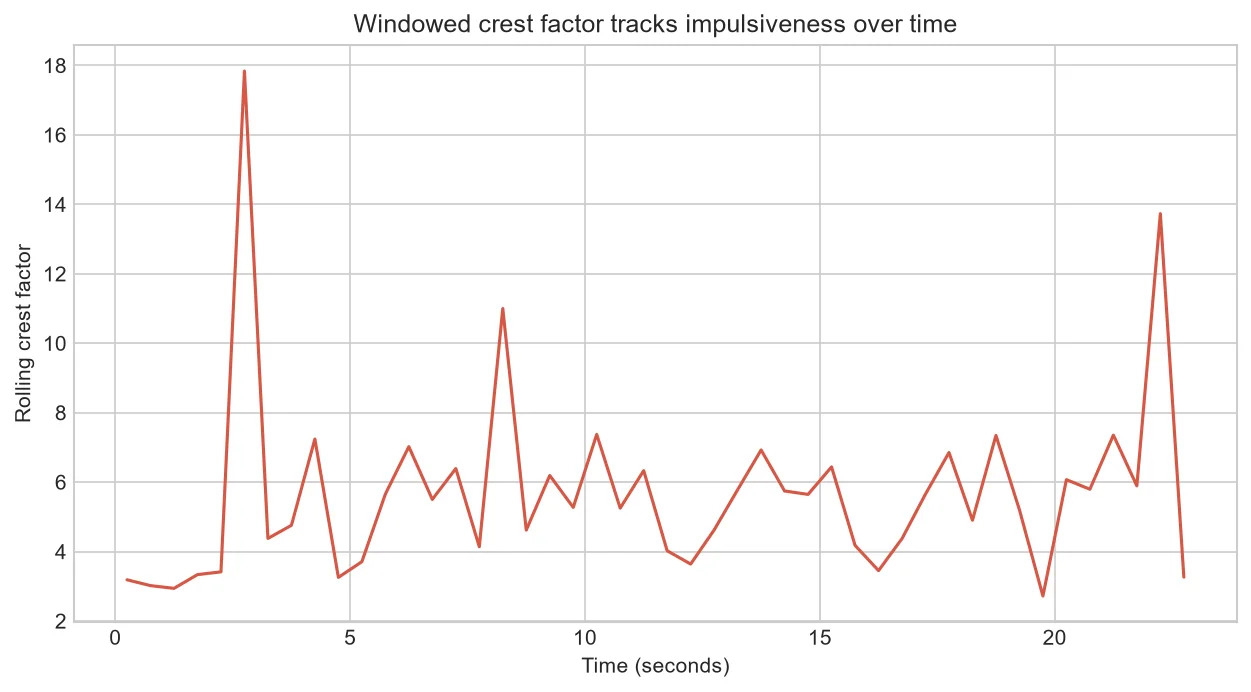
Crest factor compares the largest absolute value in a window with its RMS. It can reveal short, sharp events that a broad energy average softens, but it becomes unstable when the denominator is very small.
Why local ratios help
A full-record crest factor tells us that a peak exists but not where. A moving calculation places the event in time so it can be matched with entry, exit, reversal or an unexpected impact.
The quiet-window problem
When RMS approaches zero, an ordinary small peak can produce a large ratio. Apply a documented minimum-energy rule or mark those windows as low-confidence instead of presenting them as strong anomalies.
Read two features together
A high crest factor with ordinary RMS suggests a brief impulse. High RMS with moderate crest factor suggests broader vibration energy. Both patterns deserve different questions and inspections.
Confirm repeatability
A feature becomes useful when the same process phase behaves consistently across healthy cycles and changes persistently under a meaningful condition.
Review an apparent impact
Locate the high crest-factor window, then show one second of raw X, Y and Z data around it. Check whether the event repeats at the same controller phase.
If it occurs once in one file, record it for review. If it persists across comparable cycles, examine tool engagement, workholding and sensor attachment.
| RMS | Crest factor | First interpretation |
| Normal | High | Brief impulse |
| High | Moderate | Broad energy rise |
| Very low | High | Check denominator |
Common mistakes to avoid
- Alerting on a ratio in near-zero energy.
- Ignoring phase position.
- Calling one isolated peak a fault.
Frequently asked questions
Does a high crest factor prove bearing damage?
No. It describes waveform shape, not a unique cause.
Which axis should be used?
Review all mounted axes and preserve their orientation.
Can clipping reduce crest factor?
Yes; clipped peaks make the ratio misleading and should fail data-quality checks.
Practical workflow for this method
Combine an RMS floor with persistence and process-state filters. State every rule explicitly so operators can understand why an alert appeared.
Compare robust alternatives such as peak percentile divided by RMS when isolated electrical spikes dominate the ordinary maximum.
About the data used in this guide
The charts use a small teaching sample selected from machines M01, M02 and M03, primarily operations OP05 and OP06. The source records tri-axial acceleration at 2 kHz and labels available examples as good or bad. Label coverage is uneven across machine-operation groups, so missing groups are not treated as healthy evidence. These figures are transparent worked examples, not population estimates or universal fault thresholds.
Dataset: CNC Machining Data, CC BY 4.0. Recommended citation: Tnani, Mohamed-Ali; Feil, Michael; Diepold, Klaus. Smart Data Collection System for Brownfield CNC Milling Machines: A New Benchmark Dataset for Data-Driven Machine Monitoring. Procedia CIRP 107 (2022), 131–136. Research paper.
We explain what the selected data supports and avoid naming a mechanical fault when the dataset only provides a good/bad process label. A machine should be inspected by a qualified person before maintenance or safety decisions are made.


