CNC Condition Monitoring
How to Read X, Y and Z Vibration Data from a CNC Machine
A practical introduction to tri-axial CNC vibration data and why the strongest axis is not automatically the most important.
Three-axis vibration data can look intimidating because it gives you three answers at once. The trick is to stop looking for a “winning” axis and ask what each direction means for the sensor mounting and the machine structure.
Start with orientation
Before analyzing a trace, photograph the sensor and mark the direction of its axes. A sensor mounted on the enclosure may not align with the machine coordinate system. If it is removed and rotated, the new X trace may contain motion that used to appear on Y.
Why the amplitudes differ
Machine structures have preferred directions. A thin panel may flex more than a casting, and cutting forces change with toolpath direction. In the sample waveform, X has a visibly different range from Y and Z. That is a reason to establish per-axis baselines, not a diagnosis.
Read shape before summary numbers
Zoom into a short window. Look for impacts, modulation, repeating bursts, and sudden changes. Then calculate RMS, peak, and crest factor. Summary features are easier to trend, while the waveform preserves clues about how the change happened.
Keep the comparison fair
Use the same sensor, location, orientation, sample rate, operation, and machine state. If any of those change, record it. Good metadata prevents a maintenance team from chasing a false alarm caused by a moved sensor.
Reading the axes without guessing
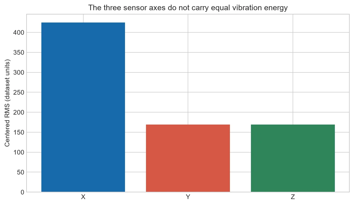
In one selected good-labeled OP01 file, centered RMS is roughly 425 on X and about 169 on both Y and Z in the dataset’s native units. That does not prove that X is unhealthy. It shows that the sensor, structure and operation transfer more measured energy along that sensor axis during this record.
A better comparison asks whether X remains near its own normal range on later matched cycles. Y should be compared with Y, and Z with Z. Combining all axes into one number too early can hide a directional change.
| Observation | Careful interpretation |
| One axis is always larger | May reflect mounting direction or structural stiffness |
| All axes rise together | Check process load, mounting and broad machine-state changes |
| Only one axis changes | Inspect directional force, structure and sensor security |
Common mistakes to avoid
- Assuming sensor X is identical to the CNC machine X axis.
- Rotating a sensor and continuing the old trend line.
- Using the same vertical scale when it hides detail on smaller axes.
- Averaging three axes before inspecting them separately.
Frequently asked questions
Which axis is most important?
The axis that changes consistently for the monitored condition. Importance is established through data and inspection, not axis name.
Can I calculate one combined value?
Yes, vector magnitude can be useful, but retain the individual axes because direction may carry important information.
Must the sensor be perfectly aligned?
Perfect alignment is less important than secure, repeatable mounting and documented orientation.
About the data used in this guide
The charts use selected files from machine M01, operation OP01. The source records tri-axial acceleration at 2 kHz and labels process examples as good or bad. Our initial charts use two files from each label. They are teaching examples, not universal fault thresholds.
Dataset: CNC Machining Data, CC BY 4.0. Recommended citation: Tnani, Mohamed-Ali; Feil, Michael; Diepold, Klaus. Smart Data Collection System for Brownfield CNC Milling Machines: A New Benchmark Dataset for Data-Driven Machine Monitoring. Procedia CIRP 107 (2022), 131–136. Research paper.
We explain what the selected data supports and avoid naming a mechanical fault when the dataset only provides a good/bad process label. A machine should be inspected by a qualified person before maintenance or safety decisions are made.


