CNC Condition Monitoring
CNC Vibration Monitoring Explained in Plain English
Learn what CNC vibration monitoring measures, what it can reveal, and why a baseline matters more than a single alarm number.
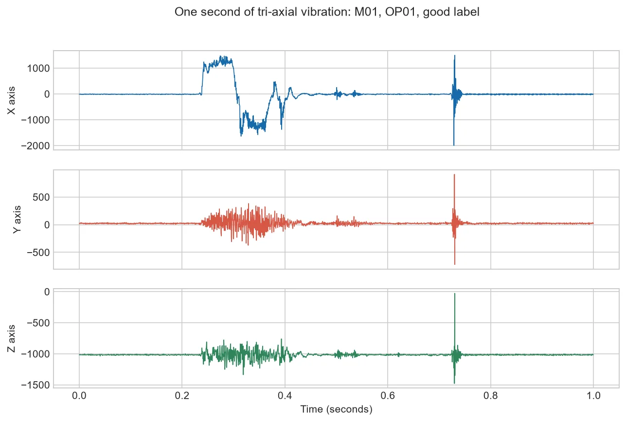
A CNC machine always vibrates. Motors turn, bearings roll, cutters enter and leave the work, and chips break away. The useful question is not “Does this machine vibrate?” It is “Has the vibration changed in a way that deserves attention?”
What the sensor actually records
An accelerometer measures motion along one or more directions. In the Bosch dataset, a tri-axial sensor records X, Y, and Z at 2,000 samples per second. That produces three time series. Peaks, repeating patterns, and changes in energy can then be compared with a known operating baseline.
Why context matters
A roughing pass and a finishing pass should not be expected to look the same. Spindle speed, feed, tool engagement, material, fixture, coolant, and sensor mounting all affect the signal. A useful monitoring system stores this context instead of treating every cycle as identical.
What monitoring can and cannot tell you
Monitoring is good at answering “Is this cycle behaving differently?” It is weaker at answering “Which component has failed?” A high reading may come from a worn tool, loose fixture, changed cut, bearing issue, or a sensor that moved. Inspection and process knowledge still close the loop.
A sensible first project
Choose one repeatable operation. Mount the sensor securely, collect several healthy cycles, and calculate simple features such as RMS and crest factor. Watch how those values vary naturally before setting any alert. This modest baseline is more useful than copying a limit from another machine.
A simple monitoring example
Imagine a cabinet shop that runs the same pocketing operation every morning. The operator records ten healthy cycles after a new tool is installed. Instead of comparing raw peaks from unrelated jobs, the shop tracks X-, Y-, and Z-axis RMS for that one operation. Two weeks later, Y-axis RMS rises above its usual band for three consecutive parts.
That change is a reason to inspect, not a diagnosis. The operator checks the tool, holder, fixture, part seating, spindle sound, and finished surface. If a loose clamp is found, the event is recorded. The next similar signal now has useful maintenance context.
| Question | Useful evidence |
| Did the process change? | Program, tool, feed, speed, material and fixture record |
| Did the signal change? | Matched waveform, RMS trend and spectrum |
| What caused it? | Inspection findings, part quality and maintenance notes |
Common mistakes to avoid
- Using one alarm value for every CNC program.
- Moving the sensor without recording its new position.
- Calling every unusual trace a bearing failure.
- Ignoring production changes that explain the signal.
Frequently asked questions
Can vibration monitoring replace inspection?
No. It helps decide when and where to inspect. Physical inspection and process evidence remain necessary.
How much healthy data is enough?
There is no universal count. Collect enough matched cycles to see normal variation across tools, shifts and expected operating conditions.
Should monitoring run continuously?
Not always. Cycle-based collection can be simpler when the operation is repeatable and machine state is available.
About the data used in this guide
The charts use selected files from machine M01, operation OP01. The source records tri-axial acceleration at 2 kHz and labels process examples as good or bad. Our initial charts use two files from each label. They are teaching examples, not universal fault thresholds.
Dataset: CNC Machining Data, CC BY 4.0. Recommended citation: Tnani, Mohamed-Ali; Feil, Michael; Diepold, Klaus. Smart Data Collection System for Brownfield CNC Milling Machines: A New Benchmark Dataset for Data-Driven Machine Monitoring. Procedia CIRP 107 (2022), 131–136. Research paper.
We explain what the selected data supports and avoid naming a mechanical fault when the dataset only provides a good/bad process label. A machine should be inspected by a qualified person before maintenance or safety decisions are made.


