CNC Thread Milling Calculator
Calculate spindle speed (RPM), feed rate (IPM), helix pitch per revolution, lead-in arc radius, and cutter offset for internal and external thread milling. Includes G-code parameter summary for helical interpolation.
Free Tool · UN / Metric Threads · Internal & External · G-Code Params · Inch & MetricOD of the thread mill body (not thread profile diameter).
Thread milling uses lower chiploads than endmilling. Typical: 0.0005–0.002 in/tooth for carbide in steel; 0.001–0.003 in/tooth in aluminum.
; Run calculator to generate G-code parameters
| Thread Geometry | |
| Thread size | — |
| Thread type | — |
| Thread pitch | — |
| Thread major diameter | — |
| Thread minor diameter (approx.) | — |
| Cutter / Toolpath | |
| Cutter diameter | — |
| Cutter offset (helical arc radius R) | — |
| Lead-in arc radius | — |
| Helix pitch per cutter rev | — |
| Z per 360° pass (= thread pitch) | — |
| Speeds & Feeds | |
| Cutting speed | — |
| Spindle speed (RPM) | — |
| Chipload per tooth | — |
| Feed rate | — |
| Approx. cycle time (1 pass) | — |
The cutter follows a helical arc around the thread axis. One full 360° revolution advances exactly one thread pitch in Z. The cutter offset R = (thread_dia − cutter_dia) / 2 for internal threads.
How CNC Thread Milling Works
Thread milling uses a rotating thread mill cutter that travels in a helical interpolation path (G2 or G3 arc with simultaneous Z movement). In a single 360° helical revolution, the cutter cuts a full thread profile and advances exactly one pitch in Z. Thread milling offers major advantages over tapping: it works in blind and through holes with the same cutter, creates no axial thrust, allows thread size adjustment with cutter offset, and is much safer in hard or exotic materials where taps often break.
1 Spindle Speed & Feed Rate
RPM is calculated from the cutter diameter (not the thread diameter) and the surface footage for your material. Feed rate (IPM) is standard chipload × flutes × RPM — same as any milling operation.
2 Cutter Offset & Helix Radius
The cutter center travels on a circle offset from the thread axis. For internal threads, the offset R = (thread_major_dia − cutter_dia) / 2. This is the arc radius used in the G2/G3 block. For external threads, the math inverts.
3 Helix Pitch per Revolution
In one full cutter revolution around the thread axis (360° of arc), the tool must descend exactly one thread pitch in Z. For a multi-start thread mill (multiple rows of teeth axially), a single helical pass cuts the full thread depth in one 360° revolution. For a single-tooth cutter, multiple passes with Z offset are needed.
4 Lead-In Arc
The cutter must enter the thread arc tangentially — not straight-line plunge — to avoid a witness mark or gouging. A 90° or 180° lead-in arc at half the cutter offset radius brings the cutter smoothly onto the thread circle before the helical cut begins.
Thread milling becomes the preferred process when: (1) the workpiece material is hard (>40 HRC) where taps break unpredictably; (2) you're making large diameter threads (over ¾") where rigid tapping torque is excessive; (3) the hole is blind and thread depth control is critical; (4) you need left-hand threads — just reverse the helical direction; (5) materials like titanium, Inconel, or hardened steel make tapping risky and expensive. The trade-off: thread milling requires a correctly programmed helical interpolation path and is slower per hole than a rigid tap cycle. For high-volume production of small threads in aluminum, tapping is usually faster and more economical.
Worked Examples
Pitch = 0.0769" Z/360° = 0.0769"
Pitch = 1.5mm Z/360° = 1.5mm
Pitch = 0.100" Z/360° = 0.100"
Common Thread Milling SFM / Chipload Reference
| Material | SFM (Carbide) | Chipload (in/tooth) | Coolant | Notes |
|---|---|---|---|---|
| Aluminum 6061 | 600–1,200 | 0.001–0.003 | Air / flood | High speed, good chip clearance |
| Mild Steel (1018) | 250–400 | 0.0006–0.0012 | Flood | Standard thread milling |
| Alloy Steel (4140) | 200–350 | 0.0005–0.0010 | Flood | Reduce SFM for harder variants |
| Stainless 304/316 | 100–200 | 0.0004–0.0008 | Flood | Work hardening risk — maintain feed |
| Hardened Steel (45+ HRC) | 60–120 | 0.0003–0.0006 | Oil mist | Use CBN or fine-grain carbide |
| Titanium Ti-6Al-4V | 60–100 | 0.0004–0.0008 | High-pressure flood | TiAlN coating essential |
| Inconel 718 | 40–70 | 0.0003–0.0006 | Flood | Very low SFM, sharp edges |
| Brass / Bronze | 400–700 | 0.001–0.002 | Dry / air | Free-machining, excellent tool life |
Frequently Asked Questions
Related CNC Calculators
Shop Ball Nose End Mills
Long-shank carbide cutters for 3D contouring, die finishing, and sign carving.
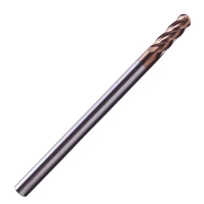
Ball Nose End Mill
R0.25–R8mm, 2/4 flutes, multiple coatings
View on Alibaba →
15-Piece Router Bit Set
Multi-size starter kit
View on Alibaba →
ER Collet Set
Precision tool holding
View on Alibaba →As an Alibaba affiliate partner, we earn from qualifying purchases at no cost to you.