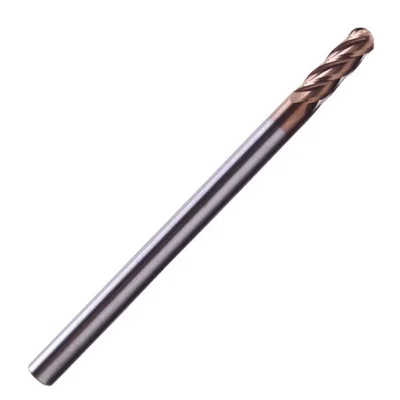
Calculate effective cutting diameter (Deff) at axial depth of cut, adjusted RPM and feed rate, cusp height (scallop), and required stepover for a target surface finish. Essential for 3D milling, die/mold work, and contour surfacing.
How far the ball tip engages the work. Must be less than ball radius (D/2). The smaller ap is relative to D, the smaller Deff becomes — and the higher RPM you need.
SFM
fzin/tooth
Surface Finish (Stepover)
aein
Distance between adjacent passes. Determines cusp height (scallop) and surface finish quality.
hcin
Enter your maximum allowable cusp height. Calculator will show the required stepover to achieve it.
Results
Effective Diameter (Deff)
—
in
Adjusted RPM
—
RPM (from Deff)
Cusp Height vs. Target—
0—target
Effective Dia (Deff)
—
2√(ap·(D−ap))
Adjusted RPM
—
Based on Deff, not D
Cusp Height (actual)
—
from stepover
Stepover for Target hc
—
to achieve target cusp
Adjusted Feed Rate
—
IPM
Nominal RPM (at D)
—
Uncorrected (wrong to use)
Deff as % of D
—
Cutting vs. nominal dia
Stepover as % of D
—
% of ball diameter
ReadyEnter ball endmill diameter, axial depth, and stepover to calculate effective diameter and cusp height.
The effective cutting diameter (Deff) at axial depth ap is always smaller than the nominal diameter D. Using nominal D for RPM calculation results in lower-than-intended cutting speed — the adjusted RPM from Deff is always higher.
Why Ball Endmill Effective Diameter Matters
A ball endmill does not cut at its full diameter unless it is plunging straight down. In 3D profiling, contour milling, and finishing passes, the cutter engages the workpiece at some axial depth (ap) that is a fraction of the ball radius. At that engagement depth, the actual cutting circle — the effective diameter (Deff) — is significantly smaller than the nominal tool diameter. Programming RPM based on nominal diameter means your cutting speed (SFM) is far below the manufacturer's recommendation, causing rubbing, poor surface finish, and premature tool wear.
1 Effective Diameter Formula
Deff is the diameter of the cutting circle formed where the ball intersects the workpiece surface at axial depth ap. It is always ≤ D, and approaches zero as ap approaches zero.
Effective Diameter:
Deff = 2 × √(ap × (D − ap))
D = nominal ball endmill diameter
ap = axial depth of cut
Example (D=0.500", ap=0.050"):
Deff = 2 × √(0.050 × (0.500−0.050))
= 2 × √(0.050 × 0.450)
= 2 × √0.0225
= 2 × 0.150
= 0.300"
→ Only 60% of nominal diameter!
→ RPM must increase by 1/0.60 = 1.67×
2 Adjusted RPM
Always calculate RPM from Deff, not from the nominal diameter. The corrected RPM will always be higher — sometimes dramatically so for shallow ap relative to D. This is the most commonly missed calculation in 3D milling.
Each adjacent pass of a ball endmill leaves a small ridge (cusp or scallop) on the surface. The height of this ridge determines surface finish quality. Smaller stepover = smaller cusp = better finish, but more passes and longer cycle time.
Cusp Height from Stepover:
hc = R − √(R² − (ae/2)²)
R = ball radius = D/2
ae = stepover between passes
Simplified (when ae << D):
hc ≈ ae² / (8R) = ae² / (4D)
Required Stepover for Target hc:
ae = 2 × √(R² − (R−hc)²)
≈ √(8R × hc) (simplified)
Example (D=0.500", ae=0.050"):
R = 0.250"
hc = 0.250 − √(0.250²−0.025²)
= 0.250 − √(0.06250−0.000625)
= 0.250 − 0.24875
= 0.00125" (0.00125" cusp)
4 Surface Roughness Estimation
Cusp height relates directly to measured surface roughness. Machined Ra is approximately 1/4 of cusp height for typical ball endmill passes. This is a geometric estimate — actual Ra is affected by vibration, chip recutting, and material springback.
Estimated Ra from Cusp Height:
Ra_est ≈ hc / 4 (geometric approximation)
Surface quality guide:
hc > 0.002" : Rough — needs finishing
hc 0.001"–0.002" : Semi-finish
hc 0.0005"–0.001": Light finish
hc 0.0002"–0.0005": Good finish
hc < 0.0002" : Fine finish / near-net
Stepover as % of D guide:
50% → rough (large cusps)
20% → semi-finish
10% → finishing
5% → fine finishing
2% → mirror-like (slow)
The #1 Ball Endmill Programming Mistake — Using Nominal Diameter for RPM
Every CNC programmer who has used a ball endmill for 3D finishing has made this mistake at least once. A ½" ball endmill at 0.030" ap has a Deff of only 0.237" — less than half the nominal diameter. Programming RPM from the nominal ½" means the actual cutting speed is 47% of the target SFM. The tool is rubbing, not cutting. Surface finish suffers, tool life is unpredictable, and increasing feed rate makes it worse. The fix is simple: always calculate RPM from Deff, not D. Your CAM software may do this automatically — check your toolpath parameters to verify.
Very shallow ap makes Deff only 46% of nominal. Nominal RPM would be 9,168 — less than half needed. Cusp height 0.000313" gives excellent finish quality.
Tiny ap on small cutter means Deff is only 35% of D. Without correction, RPM would be 6,112 — tool is rubbing. Cusp height under 0.0001" gives near-mirror finish.
Large ap means Deff is close to D (88%) — correction is less critical but still needed. Large cusp height confirms this is a roughing pass needing a finishing pass after.
It depends on the CAM system and how the tool is set up. High-end CAM packages (Mastercam, Hypermill, NX CAM) can apply Deff correction automatically when the tool is defined as a ball endmill and the axial depth is specified. Mid-range packages (Fusion 360, HSMWorks) may or may not apply it depending on the toolpath strategy. Entry-level CAM typically does not. The safest approach: always check the posted G-code spindle speed and verify it matches what this calculator gives for your ap value. If the posted RPM matches the nominal-diameter RPM instead of the Deff RPM, your CAM is not correcting — override it manually or adjust the tool speed setting in the toolpath parameters.
The maximum axial depth is the ball radius (D/2) — at that point, the center of the ball is at the workpiece surface and Deff equals the full diameter D. In practice, for finishing operations, ap is typically kept at 3–15% of D for fine surface finish. For semi-finishing, 15–30% of D. Going above 30–40% of D in a ball endmill finishing pass produces large cusps and defeats the purpose of using a ball mill for finish work. For roughing with a ball endmill (less common), ap can approach 50% of D but radial chip thinning and axial chip thinning effects must both be considered. At very high ap (>50% of R), the ball endmill behaves increasingly like a flat endmill and loses its surface-following advantage.
Because cusp height follows a square-law relationship with stepover. The simplified formula hc ≈ ae²/(4D) shows that doubling the stepover quadruples the cusp height. Halving the stepover reduces cusp to one quarter of its original value. This means that small reductions in stepover buy you disproportionately large improvements in surface finish. Going from 10% WOC to 5% WOC (halving the stepover) reduces cusp height by 75% — but doubles the number of passes and roughly doubles cycle time. The economic trade-off depends on whether your downstream finishing process (polishing, EDM, coating) can tolerate the larger cusps or requires very fine machined surfaces.
Yes — for ball endmill work, there are actually two chip thinning effects that apply simultaneously: (1) Radial chip thinning when ae (stepover) is less than Deff/2, and (2) Axial chip thinning from the ball geometry itself at shallow ap. Both act to make chips thinner than the programmed chipload suggests. In practice for fine finishing passes at shallow ap and small stepover, the combined correction factor can be 1.5× to 2.5× — meaning you may need to program significantly higher chiploads than the catalog value to achieve the intended chip thickness. Most CAM systems handle this automatically, but it's worth understanding when the posted feed rate looks unusually high for a finishing pass.